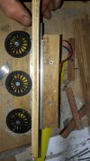
Brake compressors maybe?Just out of curiosity what are those two drum like shaped things on top of the frame?
You are using an out of date browser. It may not display this or other websites correctly.
You should upgrade or use an alternative browser.
You should upgrade or use an alternative browser.
Bringing the AA20 (Andrey Andreev 20 ton per axle) back to life...4-14-4
- Thread starter justme igor
- Start date
Or possibly Air Reservoirs for the brakes.Brake compressors maybe?
justme igor
Registered
Yes possibly for the steam break cylinder.
Pressure up no breaks, release pressure or reverse the steam in the cylinder it will brake, but no vacuum.
I think usually they hang next to the loco by the firebox outside to keep them warm(smaller ones)(google pics of steam break cylinder)
I would make sense that for bigger locomotives there is a other and bigger system, cous a loco of 20 tons total or a loco of 600 tons total.
Would not mind to have the difference in my banking account, but i would mind to put the difference in bricks around my house by hand!
justme igor
Registered
Small update:
I achieve what i wanted today, some real needed measurements.
And i am going to change the driving power, the motors are going to be in the tender for the electric variant.
It will give me some more benefits:
More motors is more power and i can make the tender more heavy for more traction thus more cars to haul. and if that is not enough i can with the same diameter wheel add more motors in a car further down the train as a "helper" same dia in wheels!
Simpler design and to work with.
But the mechanics where working as i would like, giving me that 2mm clearance i wanted! so i can make the wheel gauge a bit more realistic instead of 41mm to 43mm instead of the 45mm i would really like, but hey tis is a big loco...
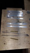
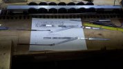
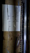
So this one went oke
But for the much needed cylinders measurement/dimensions i had to do something........
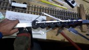
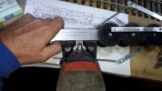
Believe it, it did not fit, so i had to "hover" the jigsaw above the frame and wheels to cut it...good luck if you want to try this and dont have enough experience with a jig saw..
I did not toke the frame apart, i just cut it with everything in place....
On the bench is a 4 meter in radii track.
The basic mechanics worked like they should work, oke not a Swiss clockwork, but what had to be done was done properly.
And i have finally some needed measurements, oke must be fine tuned...
But it drove happy back and forward, several times, with cranking up the speed i had to put some weight on the frame.
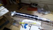
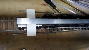
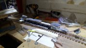
I am no photo hero, but i got what i wanted...A lot of answers to a lot of problems, lets make a AA20 4.0!(please keep in mind that live steam is the end goal, this is just play/experimenting).
I can make a groceries list for a month for a 6 person family of things that must be improved....
I will get there with a accurate and good working AA20
With best regards and thanks for reading, Igor
I achieve what i wanted today, some real needed measurements.
And i am going to change the driving power, the motors are going to be in the tender for the electric variant.
It will give me some more benefits:
More motors is more power and i can make the tender more heavy for more traction thus more cars to haul. and if that is not enough i can with the same diameter wheel add more motors in a car further down the train as a "helper" same dia in wheels!
Simpler design and to work with.
But the mechanics where working as i would like, giving me that 2mm clearance i wanted! so i can make the wheel gauge a bit more realistic instead of 41mm to 43mm instead of the 45mm i would really like, but hey tis is a big loco...


So this one went oke
But for the much needed cylinders measurement/dimensions i had to do something........


Believe it, it did not fit, so i had to "hover" the jigsaw above the frame and wheels to cut it...good luck if you want to try this and dont have enough experience with a jig saw..
I did not toke the frame apart, i just cut it with everything in place....
On the bench is a 4 meter in radii track.
The basic mechanics worked like they should work, oke not a Swiss clockwork, but what had to be done was done properly.
And i have finally some needed measurements, oke must be fine tuned...
But it drove happy back and forward, several times, with cranking up the speed i had to put some weight on the frame.


I am no photo hero, but i got what i wanted...A lot of answers to a lot of problems, lets make a AA20 4.0!(please keep in mind that live steam is the end goal, this is just play/experimenting).
I can make a groceries list for a month for a 6 person family of things that must be improved....
I will get there with a accurate and good working AA20
With best regards and thanks for reading, Igor
Greg Elmassian
Guest
So with the motors moving to the tender, your challenge will be to make the locomotive as low rolling friction as possible. A new challenge!
Greg
Greg
justme igor
Registered
Yes and no.So with the motors moving to the tender, your challenge will be to make the locomotive as low rolling friction as possible. A new challenge!
Low friction is really not a point(all ready have it), but the point is the lateral movement of the wheels.
The electric engines are keeping away the movement i would like.
For live steam this could work because the power is coming from the cylinders and thus i can have more side movement in the axles.
But mechanically it is driving "happy" on a 4 meter radii curve, but that 1mm gauge per side, or 2mm in total...i want those mm's
6 engines in the tender is technically no challenge.... time is...... in my situation.
With best regards Igor
Greg Elmassian
Guest
If you can keep a rigid frame, then you could use Aristo craft gearboxes, with tons of lateral movement. You can connect the gearboxes with ordinary hex stock.
Not trying to change your mind, but I did mention this very early on.
About the friction, with tender power, now you will be pushing the loco, so rolling friction (which includes friction from going around curves) will be very important.
Interesting to see how you proceed. (Since you seem to be able to handle the frame issue, then the Aristo gearboxes seem to be an alternative)


Notice the very wide worm gear, allows a lot of side to side axle movment

The side to side motion is about 1/8" from my measurement.
I have a 2-10-2 that traverses 8' diameter curves with these gearboxes.
(this video was a joke to the builder, by using a diesel sound board)
Not trying to change your mind, but I did mention this very early on.
About the friction, with tender power, now you will be pushing the loco, so rolling friction (which includes friction from going around curves) will be very important.
Interesting to see how you proceed. (Since you seem to be able to handle the frame issue, then the Aristo gearboxes seem to be an alternative)


Notice the very wide worm gear, allows a lot of side to side axle movment

The side to side motion is about 1/8" from my measurement.
I have a 2-10-2 that traverses 8' diameter curves with these gearboxes.
(this video was a joke to the builder, by using a diesel sound board)
justme igor
Registered
Thank you for the detailed pictures of the gear boxes, it looks similar to what i was trying to achieve for the middle wheels.(2x3...1...2x3)
Before you give me the link to convert a mp4 to a GIF i toke apart the AA20, and this numb-nuts did not make any video of the driving......f****
Incl movement with the cylinders...
Anyway here is the new plan of attack.
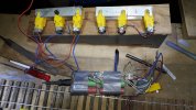
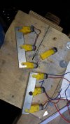
I toke all of the electronics out of the tender and i will put them in the boiler.
About the friction, with tender power, now you will be pushing the loco, so rolling friction (which includes friction from going around curves) will be very important.
For friction on the driving wheels: nothing what a good lumb of lead can not fix.
And some free rotating axles, Home made bearing type if you would like to refure to, low friction all the way, same metal on same metal, basic stuff
For basic mechanics i dont think this will change a lot, live steam or dc motors in the tender.
Pushing or pulling, it all comes down on weight.
With best regards Igor
Greg Elmassian
Guest
Igor, we all love your creative ideas.
But when you say friction on driving wheels, you say just add more weight.
Well, if the track is flat, and you have ball bearings on all wheels, then maybe true on straight track.
Really, I think you underestimate what trying to push an unpowered loco with a really long wheelbase takes.
And friction is indeed basic mechanics. I'm just trying to help, but you brush these things aside.
At the very least, your tread profile might want some revision, considering your railhead is not of a prototype shape. It is thin metal strips right? Please remind me how wide? Certainly narrower than code 332, right?
I'm not an expert in wheel tread profiles, but I have read a lot about them and have a friend who works on rail head profiles in the real world to lower friction.
Pushing is VERY different from pulling. Just ask anyone who has tried to back up a train the first time, much more difficult to push than pull.... everyone knows this including the prototype railroads.
Greg
justme igor
Registered
That is much appreciated.'m just trying to help
No, i take those things you and everybody else is/are stating or saying in to consideration.but you brush these things aside.
I try to tackle one (1) problem at the time.
Outside my hobby shed i am to occupied to have the whole build in my head and have it done in one go.
It is just aluminium strip 2mm by 10 mm/ 0.078 inch by 0.393 inch.It is thin metal strips right?
I did follow some lessens at the technical university in Delft about this subject and train rolling stuff in general.I'm not an expert in wheel tread profiles, but I have read a lot about them and have a friend who works on rail head profiles in the real world to lower friction.
There was to much info scattered around on the net.
For the bigger ones in my garden, they will have there separate track, incl a bit wider in gauge curves: 46 mm instead of 45 mm gauge/ 1,811 inch - 1,771 inchyour tread profile might want some revision
best Igor
justme igor
Registered
Oke the experimenting is going on, i tread myself on a couple of hours in my hobby shed...freaking weather...wet rain cold windy....no weather to put you upper roofing tiles into/onto cement...
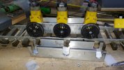
Wasted time(skid row), it is not going to work, it wont put any traction on the tracks.....
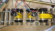
Oke lets restart again....
You see the nuts to make it a 43.5mm gauge?
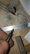
Yes small hammer and small pointing tool, my usual stuff is much bigger......much bigger
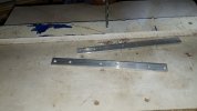
after drilling
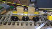
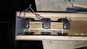
Inside the tender, i still need to cut the sluts in the bottem...
Probably i will need rebuilt the whole tender.
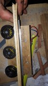
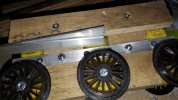
Yes a bit unclear, but i will try to explane:
The tri wood is the bottom of the tender
The alu strips are the "barrings"...simple mechanics Greg
Same metal on same metal gives no wear or friction....There are some scale's Greg..read and learn
I am thinking about to put a little lithium vet between them, experiment will show the difference!
AND I fucked up a engine....kcuf, i can take the whole lot apart to chance one engine....(i broke a wire into ONE of the engines, not repairable)
Oke my fault to work with 3th hand engines if i did not use them 6x or more
Greg be quite, please, on all of it and the rest.....
With best regards Igor K....

Wasted time(skid row), it is not going to work, it wont put any traction on the tracks.....

Oke lets restart again....
You see the nuts to make it a 43.5mm gauge?

Yes small hammer and small pointing tool, my usual stuff is much bigger......much bigger

after drilling


Inside the tender, i still need to cut the sluts in the bottem...
Probably i will need rebuilt the whole tender.


Yes a bit unclear, but i will try to explane:
The tri wood is the bottom of the tender
The alu strips are the "barrings"...simple mechanics Greg
Same metal on same metal gives no wear or friction....There are some scale's Greg..read and learn
I am thinking about to put a little lithium vet between them, experiment will show the difference!
AND I fucked up a engine....kcuf, i can take the whole lot apart to chance one engine....(i broke a wire into ONE of the engines, not repairable)
Oke my fault to work with 3th hand engines if i did not use them 6x or more
Greg be quite, please, on all of it and the rest.....
With best regards Igor K....
Attachments
Greg Elmassian
Guest
You know, you don't have to mention my name and say things like "simple mechanics", or "read and learn" it just starts bad feelings. Just leave me out of it.
(Realize that less antagonistic comments to me and better attention to making things clear and a spelling checker would be a better investment in time)
I won't ask any questions, I assume you are trying to make some kind of suspension to allow the 3 motor units to all conform to the rails to give maximum traction.
Sorry you screwed up one of your drives.
Greg
Greg Elmassian
Guest
If you are talking the rail, actually, aluminum is great stuff, because it almost immediately forms a thin layer of oxide... aluminum oxide.... next time you get sandpaper you will find 2 types, slilcon carbide and aluminum oxide...
Greg
Greg
Basic English word, can be used in any sentence.AND I fucked up a engine...
justme igor
Registered
It was meant as sort of humour, light footed and not as a insult, sorry I wrote it wrong.know, you don't have to mention my name and say things like "simple mechanics", or "read and learn" it just starts bad feelings. Just leave me out of it.
With best regards Igor
Greg Elmassian
Guest
Igor, really trying to work with you, but after our "fights", let's skip the humor and keep to technical stuff ok? One thing that does not translate well is some of our (American) expressions.
Anyway, was I right you are trying to make some sort of suspension or better termed equalization between the 3 drive motors for better traction? The ideal way is to apply the weight to the drive axles if possible, but they look to be plastic. That would be better than pressing down on the gearbox, since then you put extra strain on the axle bearings, again the concern is that they are plastic.
I sure wish I could get you some Aristo gearboxes, as they are very rugged. Perhaps you could consider using the 2 axle gearboxes, they have ball bearings, and remove the enclosed gearbox from the motor block and make the motor vertical:

These motor blocks are now available from Bachmann. You could just use the motor and the right hand drive... you cannot see easily but that enclosed gearbox has ball bearings, so it can take a lot of weight. You already have the universal so alignment of motor and gearbox no problem and you can allow the gearbox to move a bit so you can have a suspension/equalization to ensure great wheel contact. This is a proven drive mechanism, for at least 20 years. It would not be cheap if you bought 2 or 3, but definitely enough strength to pull your train and a weighted unpowered locomotive.
The wheels are all metal, so you could turn them down to tender size.
Just an idea.
Greg
Anyway, was I right you are trying to make some sort of suspension or better termed equalization between the 3 drive motors for better traction? The ideal way is to apply the weight to the drive axles if possible, but they look to be plastic. That would be better than pressing down on the gearbox, since then you put extra strain on the axle bearings, again the concern is that they are plastic.
I sure wish I could get you some Aristo gearboxes, as they are very rugged. Perhaps you could consider using the 2 axle gearboxes, they have ball bearings, and remove the enclosed gearbox from the motor block and make the motor vertical:

These motor blocks are now available from Bachmann. You could just use the motor and the right hand drive... you cannot see easily but that enclosed gearbox has ball bearings, so it can take a lot of weight. You already have the universal so alignment of motor and gearbox no problem and you can allow the gearbox to move a bit so you can have a suspension/equalization to ensure great wheel contact. This is a proven drive mechanism, for at least 20 years. It would not be cheap if you bought 2 or 3, but definitely enough strength to pull your train and a weighted unpowered locomotive.
The wheels are all metal, so you could turn them down to tender size.
Just an idea.
Greg
justme igor
Registered
Some history:
There is a 80% chance that Andrej Andrejew Andejewitsh was making the six axle to a seven axle just for Staling with his great mind set..... (to keep his family save)
I found proof in some other alterations for other things, so this also will not surprise me.
Who is he, who was he, what was he.......fill the blanks....give me please what you can find about him(all of it), this Andrej Andrejew Andejewitsh (20 tons per axle is the loco)
.
Sorry yes i am also interested in history!
With best regards Igor K

