Getting a Playmobil shuttle unit to work

Pedant-mode:
A voltage of 12V..-Sorry,it just grates.. ;)

The unit could be faulty?
The problem with checking with a meter (without a load) is that a voltmeter is a very high resistance, so you need very little current to 'see' a voltage.

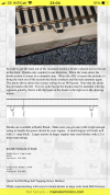
Despite it not having anything to set the delay times, I think it should be wired the same way as the filly-featured LGB unit.

Follow the breadcrumbs, to the LGB instructions:


Your controller is replacing the little unit they supply.

PhilP
No idea what has happened but I have come back into the garage to compare my setup with the LGB instructions and seen that I am set up the same.
Decided to turn power on to check for the 100th time and the train happily trundled along the length of track!
Maybe a funny connection or dirty contact who knows!?
So next question is what rating of diode would I need I believe I’ve seen 3A mentioned a few times whilst I’ve been scouring the internet?
 
Another question, now that the setup seems to be working, no matter which way the controller knob is turned the train only goes one way (guessing it’s waiting to find the diode on the track.
Anyway turned it on and off and wiggled wires to see if there was a break but all was well, then when I turned the knob the next couple of times the relay clicked twice (and I saw the arm move) and now the train will only go in the opposite direction.
I thought surely the board being of this age wouldn’t have some sort of timer in it
You are feeding power into the unit, but it is the unit that is controlling the track, so input polarity will always be the same, and the unit swaps the polarity to the track.

3A diodes should be fine..
I have a box full, bur am a little too far from you, being in the Midlands.

Depending on your skills, and how much dead electricals you have, you might be able to cannibalise something from the likes of a dead computer PSU? - Obviously, never connect the old PSU to the mains. Especially with the cover off.

PhilP.
I have the skills, just no dead electricals.
I will report back once I have a diode setup complete. Thankyou for your help!
 
Just received diodes in the post. I’ve read on another post that diodes have to be wired facing the same way, surely they should both face each other?
 
Just received diodes in the post. I’ve read on another post that diodes have to be wired facing the same way, surely they should both face each other?
The diodes are bridging the gap in the split rail so they need to face the same way so the current can flow through them. There is usually a band at one end of the diode and the current flows towards that end.
 
The diodes are bridging the gap in the split rail so they need to face the same way so the current can flow through them. There is usually a band at one end of the diode and the current flows towards that end.
I have just soldered the diodes in facing the same way on a 5ft length of track at either end.
I put the train in the middle and turn power on
Train moves in direction that diodes are facing (to the right)
Train crosses diode and stops
Nothing happens
Turn power off and relay clicks
Nothing happens (obviously no power)
Turn power on, nothing happens
Turn power off relay clicks nothing happens (train is still far right)
Leave power on and move train back to centre of track train then carries onto the right again
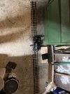
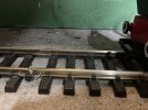
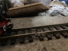
How many diodes did you install? pictures would be nice.
 
How long did you wait?

If this is an ex display (shop window) shuttle, the delay could be minutes..

I would wait for about ten minutes..
Just to see, as I believe the LGB version had two ranges, with a maximum delay of about eight minutes.


PhilP
 
I have just soldered the diodes in facing the same way on a 5ft length of track at either end.
I put the train in the middle and turn power on
Train moves in direction that diodes are facing (to the right)
Train crosses diode and stops
Nothing happens
Turn power off and relay clicks
Nothing happens (obviously no power)
Turn power on, nothing happens
Turn power off relay clicks nothing happens (train is still far right)
Leave power on and move train back to centre of track train then carries onto the right again
After the loco crosses the split track it will stop. It will stay stopped until the electonics reverse the current for the loco to return. It will then run until it crosses the other split rail, stop and then reverse the process.

Initially, on the first few runs, the loco may wait for some time but eventually the waits (in my experience) settle at between 13 and 17 seconds.

The fact that the unit clicks when you turn the power off suggests the unit is working and if you wait after turning the power back on, the loco will set off. Ideally, you use a variable controller with the unit to allow variations in speed, but what ever you use, the unit will reverse the current automatically for itself.

Watch my little video with this in mind:
 
I have just soldered the diodes in facing the same way on a 5ft length of track at either end.
I put the train in the middle and turn power on
Train moves in direction that diodes are facing (to the right)
Train crosses diode and stops
Nothing happens
Turn power off and relay clicks
Nothing happens (obviously no power)
Turn power on, nothing happens
Turn power off relay clicks nothing happens (train is still far right)
Leave power on and move train back to centre of track train then carries onto the right again
How many diodes did you install? pictures would be nice.
2 diodes
 

Attachments

  • IMG_6059.jpeg
    IMG_6059.jpeg
    367.7 KB · Views: 0
  • IMG_6060.jpeg
    IMG_6060.jpeg
    416.1 KB · Views: 0
  • IMG_6061.jpeg
    IMG_6061.jpeg
    461 KB · Views: 0
How long did you wait?

If this is an ex display (shop window) shuttle, the delay could be minutes..

I would wait for about ten minutes..
Just to see, as I believe the LGB version had two ranges, with a maximum delay of about eight minutes.


PhilP
Just turned it on and it’s sent the team to the end, just getting ready to go out so I’ve set a timer on my phone for 10mins to go check it before I go out.
 
After the loco crosses the split track it will stop. It will stay stopped until the electonics reverse the current for the loco to return. It will then run until it crosses the other split rail, stop and then reverse the process.

Initially, on the first few runs, the loco may wait for some time but eventually the waits (in my experience) settle at between 13 and 17 seconds.

The fact that the unit clicks when you turn the power off suggests the unit is working and if you wait after turning the power back on, the loco will set off. Ideally, you use a variable controller with the unit to allow variations in speed, but what ever you use, the unit will reverse the current automatically for itself.

Watch my little video with this in mind:
Thanks gotdon I’m hoping I can have mine shuttle as frequently once I sort out why it isn’t shuttling
 
Nothing happened after leaving it for over 10mins
So looks like the timer circuit has failed?

I think the IC is probably a dual packaged timer. I think it is this, or a transistor driven by it, that has failed?

It might be dry joints, but I am doubtful.

PhilP
 
So looks like the timer circuit has failed?

I think the IC is probably a dual packaged timer. I think it is this, or a transistor driven by it, that has failed?

It might be dry joints, but I am doubtful.

PhilP
Is there any way I can check this? Or should I just change the IC?
The has changed but only randomly
 
Back
Top