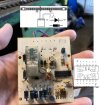
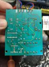
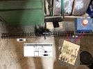
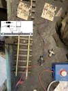
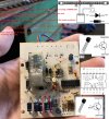
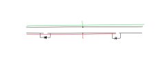
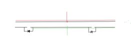
Not sure that I can see that logic of putting the diodes on the same rail is correct, but surely one at the other end should be the other way round and other rail to allow the change in polarity? Train forwards one way reverse the other, positive swops sides?Yes.
PhilP
You are using an out of date browser. It may not display this or other websites correctly.
You should upgrade or use an alternative browser.
You should upgrade or use an alternative browser.
Getting a Playmobil shuttle unit to work
- Thread starter playmofire
- Start date
I did think this because once the train crosses the diode, the diode won’t let it go backNot sure that I can see that logic of putting the diodes on the same rail is correct, but surely one at the other end should be the other way round and other rail to allow the change in polarity? Train forwards one way reverse the other, positive swops sides?
Would you recommend trying to solder a new one in?
playmofire
Registered
In my understanding the diodes only bridge the gaps in the split rails either end and the reversal of the current to cause the loco to return is done by the shuttle unit.
A
A
Maybe a long shot, but did the loco shuttle backwards and forwards while you were out of the room (I assume you didn't sit for 10 minutes watching it) and it had shuttled back to where you had left it when you returned?Nothing happened after leaving it for over 10mins
playmofire
Registered
A dry joint was mentioned as a possibilty and it might be possible to correct this one way or another. Possible cures are:
1. Check for gaps or rust on joints and clean and resolder.
2. Brush over the board on both sides with a wide, soft paint brush of the model painting sort to remove any dust or dirt which may have accumulated.
3. Wipe connections and joints with a damp cotton wool bud.
4. Spray lightly with WD40 or similar or spray this onto a cotton wool bud or similar and wipe around connections and joints. Maybe the latter to be cautious.
Do a test of the shuttle between each option.
It could’ve done I’ll give it another tryIn my understanding the diodes only bridge the gaps in the split rails either end and the reversal of the current to cause the loco to return is done by the shuttle unit.
A
Maybe a long shot, but did the loco shuttle backwards and forwards while you were out of the room (I assume you didn't sit for 10 minutes watching it) and it had shuttled back to where you had left it when you returned?
Update:It could’ve done I’ll give it another try
Tried again and sat with it for 10mins nothing happened
Tried changing power supply round (just the trackside so loco would go in opposite direction against diode direction)
Train crossed past the diode, stopped and nothing happened.
Like I said before when power is turned off/on the arm on the relay moves to the middle but then back onto the same terminal it was on (never across to the opposite side to change direction)
-bbbb
Registered
That was my intuition as well. It's how I would have attempted without instructions, and without playmofire confirming the correct operation with his identical unit. I wonder if the relay has gone bad; bad relays happen in industrial automation. Maybe he could test the relay component with a DMM. I wonder what would happen by switching the diode as you suggest. Putting the reversed diode on the other rail wouldn't make a difference unless the original one on the first rail was removed. But the scenario could be tested simply by merely reversing the section of track with one relay on it.Not sure that I can see that logic of putting the diodes on the same rail is correct, but surely one at the other end should be the other way round and other rail to allow the change in polarity? Train forwards one way reverse the other, positive swops sides?
Last edited:
playmofire
Registered
Where is the power coming from? usually there would be an all in one transformer/controller taking power from the mains or a separate transformer fed fom the mains and feeding into a controller.Update:
Tried again and sat with it for 10mins nothing happened
Tried changing power supply round (just the trackside so loco would go in opposite direction against diode direction)
Train crossed past the diode, stopped and nothing happened.
Like I said before when power is turned off/on the arm on the relay moves to the middle but then back onto the same terminal it was on (never across to the opposite side to change direction)
playmofire
Registered
Thanks, Phil.Image in post #29 shows the controller..
PhilP
Software Tools
Registered
Not sure that I can see that logic of putting the diodes on the same rail is correct, but surely one at the other end should be the other way round and other rail
The diagram is correct, and only one rail needs to be gapped.
Ok bit of learning for me, does the blocking action of a diode not care whether positive or negative current is flowing?The diagram is correct, and only one rail needs to be gapped.
The Shed
Citizen of the Republic of the North East.
More or less....Ok bit of learning for me, does the blocking action of a diode not care whether positive or negative current is flowing?
An attempt at a very simple non technical explanation......
Starting with the transformer speed controller, set direction (personal choice as to whether one chooses forward or reverse) set speed dial for desired level.
The Relay, for those familiar with a DPDT Reversing switch will recognise the similarities in the drawing above, the subtle difference is in the way the "IN" and "OUT" are connected, with a manual switch you the operator physically move the switch, in this instance is is done electronically.
For simplicity sakes will use the contacts "NC" as forward and the contacts "NO" as reverse, or could be reverse and forward.
Track connections BLUE and RED, these can be either one or the other, as in one will be POS the other will be NEG, depending on which way the Relay has been set.
The two diodes, again for simplicity refer to them as detectors, and as above they will either be conducting as POS or NEG.
The Brains is the Quad NAND Gate, which responds to what occurs with the diodes.
So for simplicity at the "A" end, the BLUE wire is POS, upon the Engine passing the diode, a pulse will be triggered to 1 of 4 of the INPUTS to the NAND Gate, which in turn will then activate the Relay, say for argument's sake the contacts will move from "NC" to "NO"
Likewise if the BLUE wire is NEG, upon the Engine passing the diode, a pulse will be triggered to 2 of 4 of the INPUTS to the NAND Gate, which in turn will then activate the Relay, say for argument's sake the contacts will move from "NC" to "NO"
Same and repeat at the "B" end, BLUE wire POS 3 of 4 of the INPUTS to the NAND Gate, and activate the Relay.
"B" end, BLUE wire NEG 4 of 4 of the INPUTS to the NAND Gate, and activate the Relay.
Phew.............
Last edited:
Erm blub blub blub, sorry that really confused me.More or less....
An attempt at a very simple non technical explanation......
Starting with the transformer speed controller, set direction (personal choice as to whether one chooses forward or reverse) set speed dial for desired level.
The Relay, for those familiar with a DPDT Reversing switch will recognise the similarities in the drawing above, the subtle difference is in the way the "IN" and "OUT" are connected, with a manual switch you the operator physically move the switch, in this instance is is done electronically.
For simplicity sakes will use the contacts "NC" as forward and the contacts "NO" as reverse, or could be reverse and forward.
Track connections BLUE and RED, these can be either one or the other, as in one will be POS the other will be NEG, depending on which way the Relay has been set.
The two diodes, again for simplicity refer to them as detectors, and as above they will either be conducting as POS or NEG.
The Brains is the Quad NAND Gate, which responds to what occurs with the diodes.
So for simplicity at the "A" end, the BLUE wire is POS, upon the Engine passing the diode, a pulse will be triggered to 1 of 4 of the INPUTS to the NAND Gate, which in turn will then activate the Relay, say for argument's sake the contacts will move from "NC" to "NO"
Likewise if the BLUE wire is NEG, upon the Engine passing the diode, a pulse will be triggered to 2 of 4 of the INPUTS to the NAND Gate, which in turn will then activate the Relay, say for argument's sake the contacts will move from "NC" to "NO"
Same and repeat at the "B" end, BLUE wire POS 3 of 4 of the INPUTS to the NAND Gate, and activate the Relay.
"B" end, BLUE wire NEG 4 of 4 of the INPUTS to the NAND Gate, and activate the Relay.
Phew.............
Software Tools
Registered
That much I understand, but I was confused if negative power flows through the diode as would positive. Your diagram appears to show that it indeed does. On that logic surely the diode to the left should be the other way round to block the negative flow as your diagram appears to intimate?The polarity on the track changes, to control the direction of movement of the loco. The diagrams below might help....View attachment 322432View attachment 322433
JimmyB
Now retired - trains and fishing
Jon it is that the power is applied in the centre track, so each diode has opposite faces, facing the power; that being either negative or positive. If one diode was the other way around then either power would flow to both ends or neither ends, depending on which way the diodes were and which way the power was applied.That much I understand, but I was confused if negative power flows through the diode as would positive. Your diagram appears to show that it indeed does. On that logic surely the diode to the left should be the other way round to block the negative flow as your diagram appears to intimate?

