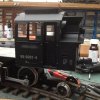
Harz Mallet Bash from Newquid Body and 2 x 20231.2 Chassis. Battery Powered.

dunnyrail

DOGS, Garden Railways, Steam Trains, Jive Dancing,
Staff member
GSC Moderator
Country flag
Having bought the two USA Locomotives to be used for the Chassis of this Loco for a silly price in York some time ago, their day has finally come. In the interveneing period I aquired a Newquid 2-6-2 Battery Loco and always looked like a part donor Loco for this project. Here are a couple of drawings of what I am aiming to achieve, though only as a look alike.
image.jpeg
image.jpeg
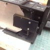
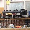
Here is a lash up of the Chassis and the Body from the Newquida Loco showing the work to do.image.jpeg
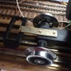
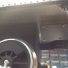
First Job is to sort out the Pivot Points and the Lump of Metal that will join the 2 motive power parts together as a Base Plate. I used a couple of 6 BA Nuts and bolts into the Wheel Holders on the Chassis as joining Piviots. Where they have been fitted there are no important running parts close to where the Bolt fits underneath the cover.
image.jpeg
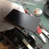
I lucked out with a nice bit of Ally in stock around 10cm wide and long enough for the Base Plate. This will be all but invisible on the completed Locomotive and the Body will be hung onto Plasticard Screwed to the Base Plate.
image.jpeg
Next was to do the R1 Reverse Curve Test before any further irreversible to base alterations took place. This as can be seen being successful I can now move forwards with the Bash. Note how the dimples beneath the Base Plate which are the Top of the removable LGB Chassis support the Base Plate without any twisting. I am confident that a slightly loose fitting Set of Top Nuts will allow any Track Twist to be negotiated with success and no wobble of the Body.
image.jpeg
Showing the Gap between the Power Bogies on an R1 Curve.
image.jpeg
Placing the bodywork on top of the Base Plate it is clear that the hight will be too great, this was something that I expected and which is why the Base Plate is narrow enogh to be outrigged by the cab.
image.jpeg
Having Razor Cut the Cab from the main body it was possible to rough up how things would look again and to check heights against the LGB Loco on the right. Note that the cab will be slightly behind the final Driving Wheel and Chassis. I have also lucked out with some Black Drainpipe that can be used to extend the Loco. I have put a request in for an old Newquid Body or Boiler Parts, but if nothing turns up I will be able to use this Drainpipe.

From this picture you can see the liberties that I will be taking with the Locomotive. No Walchearts Gear (4 sets oh no no way) and the Drivers are way too big. Not the first time such liberties have been taken. But my excuse is that this was for a different task, not Lumping up the Broken but to speed up Trains in the Trans Harz and Selktalbahn! Believe that or not but it will be a big lump of Locomotive roughly the same length as my Harz 2-10-2's.image.jpeg
Next job was to sort out the rear Pony Truck. The Pivot Point was cut from the Rear Power Chassis as seen below. At this stage opportunity was taken to remove all the Track Wipers and Slides as this is to be a Battery Queen.
image.jpeg
The rear pony spigot was cut a little and fitted with the pony using an 8BA Nut and Bolt to the rear lip on the Chassis.
image.jpeg

image.jpeg
So now we have pretty much a workable Chassis and the basics of a Body. More to come soonish.
 

Attachments

  • image.jpeg
    image.jpeg
    445.6 KB · Views: 0
Last edited:
Watching this one with interest,keep posting,,,,,,soonish;););)
 
Was that the Borsig Jon. Ended up in Brazil I seem to remember.
 
Nice work
 
I will be cheeting on the motion I think just leaving it as is. Not much progress as I have been in Watchet for two and a bit weeks but once I get some more bits things will start to happen again, many thanks for all your encouragement. Interesting to hear that one may have ended up in Brazil. If so wonder what happened to it, could be rusting away in a Shed somewhere?
 
Last edited:
Sorry Jon. It was the 0-6-6-0s that ended up in Brazil - the 2-4-4-2s were scrapped in Germany.
 
Sorry Jon. It was the 0-6-6-0s that ended up in Brazil - the 2-4-4-2s were scrapped in Germany.
I thought that the 2-4-4-2's were cut at Gorlitz or somewhere in the East but did not like to comment too quickly as I am still taking stock after my G Central near 3 week break.
 
The grotty weather yesterday and today has allowed a little more work while I wait a second NQD Body from Ebay Mike, thanks for the offer will be most useful. Twil also give me the opportunity to put a Coal Top on my Electric 2-6-2t.

Here you can see the mess created on one side whilst Pipe Detail was being removed. I intend to do all new pipe runs with Copper Mains Cable Wire. The old plastic detail has been removed predominantly with a very sharp Wood Chisel very carefully, best to work away from you with the body proped up against the work bench with hands behind where you are working. Sundry small files, nail sanders and glasspaper have been used for the tidy up as can be seen in the second pic.
image.jpeg
Once an undercoat spray has been done when the 2 bodies have been lashed together I will see what needs to be filled to tidy things up some.
image.jpeg
Here are the two Mains Plug Rubber Bungs bought for 10p at my local friendly Electrical supply show. Wires from the Motor Blocks will be threaded through the bungs ince suitable holes have been drilled in the Ally Plate.
image.jpeg
The 2 Bogies have been fitted up with couplings, this may be useful info for anyone with a 20231 Chassis that they need to fit LGB Couplings to the front bogie of.

I have salvaged a couple of varying makers loops, cut off al the rear detail so that just the loop and back section are left. This was drilled to clear 12 BA screws and mounted to the 40x8x1 mm piece of Nickel that I used. Similar 12 BA screws have been used on the Rear Holding Holes but just a screw tapped into the Plastic at the front to keep things in place due to the proximity of the Axle on the LGB Bogie. The rear bogie one has been bent down a little to match the Coupling on my Test Van, front one was ok as fitted.
image.jpeg

image.jpeg
Note I like my Vehicles Hook to be depressed slightly to Loco Coupling, though this Vans one is drooping somewhat.
image.jpeg
 
The grotty weather yesterday and today has allowed a little more work while I wait a second NQD Body from Ebay Mike, thanks for the offer will be most useful. Twil also give me the opportunity to put a Coal Top on my Electric 2-6-2t.

Here you can see the mess created on one side whilst Pipe Detail was being removed. I intend to do all new pipe runs with Copper Mains Cable Wire. The old plastic detail has been removed predominantly with a very sharp Wood Chisel very carefully, best to work away from you with the body proped up against the work bench with hands behind where you are working. Sundry small files, nail sanders and glasspaper have been used for the tidy up as can be seen in the second pic.
View attachment 235617
Once an undercoat spray has been done when the 2 bodies have been lashed together I will see what needs to be filled to tidy things up some.
View attachment 235618
Here are the two Mains Plug Rubber Bungs bought for 10p at my local friendly Electrical supply show. Wires from the Motor Blocks will be threaded through the bungs ince suitable holes have been drilled in the Ally Plate.
View attachment 235619
The 2 Bogies have been fitted up with couplings, this may be useful info for anyone with a 20231 Chassis that they need to fit LGB Couplings to the front bogie of.

I have salvaged a couple of varying makers loops, cut off al the rear detail so that just the loop and back section are left. This was drilled to clear 12 BA screws and mounted to the 40x8x1 mm piece of Nickel that I used. Similar 12 BA screws have been used on the Rear Holding Holes but just a screw tapped into the Plastic at the front to keep things in place due to the proximity of the Axle on the LGB Bogie. The rear bogie one has been bent down a little to match the Coupling on my Test Van, front one was ok as fitted.
View attachment 235621

View attachment 235622
Note I like my Vehicles Hook to be depressed slightly to Loco Coupling, though this Vans one is drooping somewhat.
View attachment 235620
Going well Jon, how low do place the loops? Had also wondered about using wire loops to be less visable?
 
Going well Jon, how low do place the loops? Had also wondered about using wire loops to be less visable?
The Couplin Loops is what I believe you mean. They are held in place with the 2 12ba screws that can be seen. I had considererd using wire loops but this can be a problem when propelling stock as it can easily be riden over by a Vehicle coupling, particularly if a longish rake is being propelled through a set of points. Pic below helps to clarify tye Coupling mids and means if attachment some.image.jpg
 
The weather being somewhat poor today has helped this on a little. Having got a second body as mentioned earlier I decided to start the next process. First to tax my brain was fitting the Cab as this would define the eventual length of the Boiler and Smokebox prior to the great Razor Saw Cuts required. Turned out to be easier than I thought it would be.

A Plastic Extension (30 thou for strength) was fabricated to sit under the NQD cab with a shade taken off the bottom of the rear of the cab to enable the original Screw Hols to be used. Below you can see the screws into the NQD Cab Rear and the Brass Tube 6mm square used to block it down to the required location. The main fabrication has been bolted to the ally plate with 12 BA Nuts and Bolts. The Black Screws on the ally just underneath the K are holding to the inside fabrication on the cab see later.
image.jpeg
Underneath view of the fabrication prior to fitting and drilling holes to fit to the cab.image.jpeg
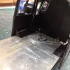
The cab itself has had some Plasticard welded inside to act as furter support and help define the height that the Boiler will match to. These together with some strengthening gussets can be seen in the next pic. The Cab door opens somewhat below this and some meat has been taken outvof the Ally Plate to allow this. A dropped floor will sit in this area.
image.jpeg
Whilst playing about with all this I noticed that the Chassis was touching the front end of the supporting Brass Square, but I needcnot have worried as the nextvtwo pics show there is plenty of clearance for R1 running. Phew.image.jpeg

image.jpeg
Having done all that it was time to ruin another NQD body by cutting out the Boiler from the Cab and Tanks. This was then offered up to see just where I needed to shorten it to get my required new Boiler. As can be seen from below the finished product will be very much a pimplier beast than the prototype that I am basing this on. And yes it will have 2 Domes and Sand Boxes just like the Harz 2-10-2's. The pic below is a rough to show how the boiler will look. Side tanks will of course hide all the fresh air beneath the boiler. I do not anticipate any problems fitting Bateries or Control Gear to this lump.
image.jpeg
Next up clean off all the pipework from the second boiler and they will then be ready to weld together.
 
Yesterday saw a little more work to add to the odd jobs being carried out in a derisory way during the rainy period we are having in UK. I have been filing cutting and generally bashing all the pipework off the two boiler sections. Having completed this some filling was required, that being done dried and sanded off it was time to join up the two Boiler Sections. As said earlier this will not be an exact copy and as the length is so great I needed most of the Boilers lengths to make up the new boiler. Only the Smokebox on one has been discarded.

Pic below shows the work to the inside prior to joining the Boiler Sections, many off cuts of Plasticard but made to size sonthat the Boiler will sit on the Plate.image.jpeg
Boiler joined and the section filled with Plastic Putty.image.jpeg
Now time to attack the Side Tanks, I decided to use the 4 sections that I had previously cut off the Boilers and make these up into 2's to create the extended water tanks. Inside strengthening can be seen here, helps to have a box of Plasticard Off Cuts rather that keep on using new for these jobs.image.jpeg
The two sections joined, will need some fill at the joints and some plasticard sections to fill in the two divits on each section.image.jpeg
Finally a view with the Tanks roughed up in place before some more work.image.jpeg
At this stage some of the many jobs to do are very apparent, big gaps that will need some sort of fill and detail. Also the front end will need a buffer beam. Then there will be all the pipework oh and Control System as well. Still lots to do!
 
Rubbish weather today has seen a good bit of progress and a little back stepping with a couple of things to be redone. First I was keen to get the Side Tanks fitted to the Ally Plate, this was done by using the original screw pegs that held held the body in place on the original Newquida job. Inevitably I had cut a couple of them down so they had to be made up with the cut off bits that I had fortunately saved in the box of stuff kept for this conversion. Below can be seen one of the pegs with the marking out to enable holes to be drilled for fitting screws, 4 holes to be got right - not achieved at the first drilling!image.jpeg
Below you can see one of the two cross braces that have been inserted to tie the two Tanks Sides together, this one having space beneath it for future wire runs.image.jpeg
Here I am fitting in place the front Tank Bottom Footplate showing off my nice brass holders that I think Phill was so interested in when someone else was using some recently on a Building. The Green and Blue pegs are holding in place some fill for the bottom of the Tank Front. The other cross support can be seen just behind the front brass thing. Tje Footplate is also glued up tomthe Tanks somthey should all be pretty secure with lots of extra bits of Plasticard off cuts to make all the joins good and secure.
image.jpeg image.jpeg
Below you can see how I have joined the two Tank Sides together and filled the gap with a piece of Plasticard off cut and lots of filling putty. Tne other side is a mirror image of this one.image.jpeg
The Boiler in place now with a bit of detail at the front. The rivets came from the bottom of the Smokebox casting and were cut off and glued on to the detail part individually. Masochist or what?image.jpeg
I have also started on the front bogie detail (seen above with the extra nickel silver strip to extend the coupling holder) but this has shown that I need to extend the coupling holder somewhat, this may need to be done also to the rear bogie.

I have roughed in place part of the under cab detail from the Newquid Loco and this will probably work fine in the location shown with some more fill behind it to hide some awfully large area of fresh air. There will also need to be something or other in the gap between the two power bogies but this will need to allow for the movement on R1 Curves, not that it will be running on any on my line but it is always nice to make that provision, LGB always did.

Many years ago I saw a super film of an Indonesian Malett running on not so perfect track with a front footplate moving from side to side very majesticaly, I am hoping that my small footplate coupled to the front pilot will replicate this in my what can now only be described as Freelance Harz like Mallett.image.jpeg
 

Attachments

  • image.jpeg
    image.jpeg
    530.3 KB · Views: 0
Back
Top