Possible motor problem with Bachmann Lyn

Looks like it has had a transplant already then. I still stand by what I said, usual belt and braces job with an old electric motor - clean the commutator and check and clean the motor brushes and springs. If you can get them replace the magnets - the people who offered re-gaussing services might be long gone. Economically, time for another transplant ? One of the first locos I had was one of these. Very simple construction with cast metal weights in the side tanks. The dummy valvegear was a bit wobbly with wear. It could haul my 3 full length GRS L&B coaches, so no lack of adhesion or grunt. Max
 
A number of things occur to me:

The LGB replacement Buhler motors are around £55 to £60, so they make the Bachmann replacement motor / gearbox combo look like good value, although the then have all the on-costs.

The other things is whether, with con rods, albeit plastic, you need a double ended motor. Could you manage a transplant with a single axle gearbox? Axle diameter then can become an issue, but it's worth investigating.
 
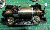
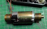
Further info. The motor is definitely Buhler. If it's a transplant then it's an extremely good match as it fits the mountings in the block perfectly - including the notches at one end to stop it from rotating.
S1760012.JPGS1760015.JPG
 
Now here's a further conundrum. Until now, my test running of the loco has been forwards. When I tried the original Lyn in I noticed it was sluggish but put it down to the sub-zero weather at the time.

I've just tried another test run and noticed the loco pulls better in reverse than going forward. It's almost (but not quite) passable in reverse though as you can see (and hear) from the video I'm having to run the loco at full pelt (3 x 3.7v li-ions). However, going forwards, skin and rice pudding springs to mind!

I've removed the motion for this run to eliminate that as a possible cause. So why does it run better in one direction than the other?


Rik
 
Last edited:
That looks to be an older motor?

As it is a transplant, I would guess a combination of wear (mainly run forward) and possibly end-play, are the problem?

Devil's advocate :
Mount the motor the other way round?

I would also make a guess, the motor may be pulling a significant amount of current?
Stall Current could be in the region of 5 Amps for the motor?

PhilP
 
If you kill the sound...

Does it stall, or is the motor running and the gears slipping?

PhilP
 
That looks to be an older motor?

As it is a transplant, I would guess a combination of wear (mainly run forward) and possibly end-play, are the problem?

Devil's advocate :
Mount the motor the other way round?

I would also make a guess, the motor may be pulling a significant amount of current?
Stall Current could be in the region of 5 Amps for the motor?

PhilP
I checked the current. It runs freely at around 0.1A and stalled at about 1.5A
Not sure if I can mount the motor the other way around as there are lugs inside the clamshell to stop the motor from rotating and they only engage with the indents at the end where the brushes are.

Rik
 
If you kill the sound...

Does it stall, or is the motor running and the gears slipping?

PhilP
No, definitely stalling. I've tried running it on the bench and holding the wheels - the motor does stop turning

Rik
 
With Buhler motors around £55 - £60, it might be worth looking at other double shaft types like Maxon. Getting it to fit shouldn't be beyond the wit of a man of your calibre with a 3D printer :p:p
 
It could just be the photo, but the clearance between the motor body and the drive cog looks really tight on the right hand side as pictured.
Now this is just a theory, but, if the axle shaft or where it passes through the motor block is worn, potentially you could get horizontal movement that might be enough to result in the cog rubbing against the motor body causing friction. If the clearance between the motor body and the drive cog is different at each end, this could explain why it has less tractive effort in only one direction.
May just be worth checking for any wear on the cog teeth and motor body to see if this is possibly happening.
Paul.
I'll give anything a try. I'll check it out and get back

Rik
 
Agreed!, and the right hand motor end looks like it was ground/filed down there for clearance with the worm gear, can you confirm what I see in that picture? There is a part of the metal motor end that looks like it has already been modified for clearance.

Hard to believe this is stock, since not only the fact that Bachmann never used Buhler motors, the worms are not centered above the worm gear, no one would ever design a gearbox like that.

413109_S1760012.jpg
 
I think the motor to worm gear clearance is possibly a big issue, note that the motor will move forwards or backwards in the housing depending on direction (thrust).

That could create contact and friction... also agreed, your "thrust bearing" is not a nice little ball bearing, but looks to be the flat end of the worm gear, which indeed could cause friction.

Greg
 
Remember he said one of the gears did not look too good, hmmm.... that could be the "not so good" one...

Compare the slots where the ends of the motor shaft (actually extension of gear) rides... on the right side it looks like a "T" sideways, now look at the left side... you can see there is more play vertically for the shaft, which might let the worm disengage from the worm gear a bit. That would certainly explain why the left worm gear looks more worn.

I think it's time for a new gearbox....

Greg
 
I think the motor to worm gear clearance is possibly a big issue, note that the motor will move forwards or backwards in the housing depending on direction (thrust).

That could create contact and friction... also agreed, your "thrust bearing" is not a nice little ball bearing, but looks to be the flat end of the worm gear, which indeed could cause friction.

Greg
Agreed. that motor shaft does look very tight to the casing.
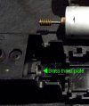
Looking at the T shaped moulding, it could just be a grease reservoir as it's the wrong shape for a ball bearing, but I suspect that it was actually designed to hold a flat metal disk to act as a thrust / end float control plate. Playmobil used a very similar system instead of a ball bearing. See below.
thrust plate playmobil.jpg
If the problem is related to motor shaft binding against the casing, shortening the motor shaft and installing a similar thrust plate in the rebates could help control it.
Nb: The angle of the photo makes it quite difficult to judge clearances, a pic of the block taken at the vertical would make it a bit clearer.
 
Last edited:
Back
Top