Possible motor problem with Bachmann Lyn

So:
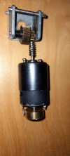
Looks like the original motor got hot. - Bulging block. From experience the motor fails by melting brushes/holder.
The block has been 'modified' to take a different motor. - Sort-of works. Probably not a fault of the motor?
The block is a little 'iffy'. - Chewed up mountings etc.
Even if we can get an original motor, they are not particularly good. We don't have the 'thrust-blocks' (I assume?).


I think (if I had a 3D printer):
I would look at making my own motor-block?
Possibly using the original wheels??

OR

Find another 'donor' on evilBay??? :wondering:

PhilP.
 
There's still a motor/gearbox unit available on the Bachmann estore spares site - shipped to the UK and taxed it'll probably cost more than Rik paid for the loco in the first place :worried::worried::worried:
 
There's still a motor/gearbox unit available on the Bachmann estore spares site - shipped to the UK and taxed it'll probably cost more than Rik paid for the loco in the first place :worried::worried::worried:
I doubt it is for a 'vintage' model?

Guessing it will be for the new run? - The body mouldings are the same, but I believe the motor-block is different.. I do not know if it could be made to fit?

PhilP.
 
I doubt it is for a 'vintage' model?

Guessing it will be for the new run? - The body mouldings are the same, but I believe the motor-block is different.. I do not know if it could be made to fit?

PhilP.
No, it's got to be the later run, but externally it looks similar - I wasn't sure whether Rik has a new or old one :think::think:
 
At the risk of getting my wrists slapped by the experts, again - Looking way back to my long gone slot racing days (50 years and counting) we used to do a lot of playing around with 16D can electric motors - hot armature winds, extra strong magnets, commutator advance/retard, shunted brushes, etc. Rik, you say the motor runs fine and pulls well in one direction, reverse the rotation/polarity and it is gutless.

My thinking here is there is a possibility that the motor's commutator has rotated out of position on the motor's shaft giving an exaggerated advance effect in one direction (polarity) and retardation in the other, usually done to tune for torque output or outright speed. Ally that to the usual old motor blues and you possibly have the situation as presented.

While not stock the replacement motor installation has the required thrust plates in place so there should be no movement on the motor shaft and mesh with gears affected by that. If the spur gears were badly worn, due to predominantly one direction use in the past to create the issue in one direction only, that would show on the gear teeth - there is nothing obviously abnormally worn there and it's the motor that stalls in one direction of rotation only. Just a thought.

By the way how are the worm gears mounted on the motor's shaft ? I had a problem with my Roundhouse Criccieth Castle manifest itself in a near identical manner, but that only has a single worm drive gear and RH diagnosed a gear mounting issue. Max
 
Hi guys
Thanks for your deliberations. Some interesting propositions and suggestions. Looking at the exploded diagram, it's clear the motor and mountings differ from my version. Those are brass bearings on the ends of the shaft. They fit neatly into the clamshell moulding so I assume they are original unless they have been machined to fit. They don't resemble the bearings in the diagram.

The photo might be deceptive as the worms are only resting loosely in the bearing holes because the wheels have been removed. I'll reassemble carefully and check to see if there's any slop and if the worm wheels rub against the motor casing. It might explain why the loco runs better in one direction than the other.

A thought. The biggest difference between this motor block and the LGB blocks I've used up to now is the diameter of the worms. If I redesigned the casings to take a motor with smaller worms, will that improve the amount of torque between worm and worm wheel? My basic knowledge of mechanics suggests this would work. I just hope Bachmann gears are standard.

Rik
 
No, it's got to be the later run, but externally it looks similar - I wasn't sure whether Rik has a new or old one :think::think:
You can easily tell the difference between original and later locos by looking at the wheel cranks. Original cranks were made from fairly thin pressed steel as per part number 81500-63 in Jimmy B's post number 39. Later cranks are more substantial castings. I don't know if early cranks will fit on later axles. May be an issue if a new replacement chassis doesn't include rods and cranks.
 
You can easily tell the difference between original and later locos by looking at the wheel cranks. Original cranks were made from fairly thin pressed steel as per part number 81500-63 in Jimmy B's post number 39. Later cranks are more substantial castings. I don't know if early cranks will fit on later axles. May be an issue if a new replacement chassis doesn't include rods and cranks.
OK, just been back there and Rik's is an early one. The later one only drives one set of axles and has a flywheel on the motor, and better reduction gears.

So, that means that it's another chassis mod for Rik.

So, Rik - what's the axle diameter?
 
View attachment 281664
For what it's worth, this is a picture of the later motor/ gearbox (2013)
Yep, that's what I deduced from the picture on the Bachmann website.

So, like wot I said earlier, any new motor / gearbox combo that Rik can make doesn't have to be a double driver - the con rods can deal with that :nod::nod::nod:
 
I checked the current. It runs freely at around 0.1A and stalled at about 1.5A
Not sure if I can mount the motor the other way around as there are lugs inside the clamshell to stop the motor from rotating and they only engage with the indents at the end where the brushes are.

Rik
Just checked one of mine with which I have had no problems; starts at about 0.1 amp and stalled at about 2.2. That would seem to be too great a disparity to be explained as a random variation. Have you had a look at brushes and possibly coil insulation problems?
 
There's still a motor/gearbox unit available on the Bachmann estore spares site - shipped to the UK and taxed it'll probably cost more than Rik paid for the loco in the first place :worried::worried::worried:
It's £78 Inc postage ....... Slightly below what I paid for the loco. ...... Dilemma!!

Do I faff around trying to bodge a repair or go for this solution?

Rik
PS How much tax will be slapped on when it gets here?
PPS Looks like it'll be 20% VAT = £15.60 it's getting less attractive. :(
 
Last edited:
..... what's the axle diameter?
Not that easy, unfortunately. Each wheel has a short square section stub axle which slot nto the nylon worm wheels.

Rik

PS looking at the pic of the new motor and gearbox, it looks like I'd also need to buy a new wheel/ wormwheel set if I wanted to use the new motor block. So, it'll have to be a bodge job
 
Hi chaps
Many thanks for all your observations and suggestions. I think I might have fixed it ........ maybe!

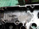
It seems that those who commented that the Buhler motor was a later addition were indeed correct. Once I cleaned up the insides of the motor block housing, it was clear that the original motor mounting had been filed away to accommodate the bigger motor.
IMG_1627.JPG

As Greg pointed out, the edges of the motor have had been filed down to ensure they cleared the worm wheels
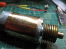
IMG_1626.JPG

Whereas I believed there were lugs to keep the motor from twisting, it turned out they were imaginary. As a consequence, the motor moved slightly when under power. By watching carefully, I could see that the can swivelled just enough to touch one of the worm wheels when the loco was moving forwards. My quick fix was to install a self-tapping screw in the motor block housing so it engaged one of the depressions in the motor can - thereby preventing it from swivelling.

As you can see from today's video, she now runs as well (or as badly) forwards as she does in reverse.

My next job is to design and 3D print a new clamshell housing to replace the Bachmann original which is slowly disintegrating. The plastic is very brittle leaving all the pillars for the self tapping screws holding it together in a cracked and precarious state.

Once again - many thanks to all those who contributed to this discussion. I was extremely helpful - and a prime example of how useful forums like this can be.

Rik
 
Yay! As I posted, that ground away area on the end of the motor was a big tipoff to me, but was not thinking that the motor was rotating, but now you mention it, there was nothing keeping it from rotating except friction.

It's too bad that you cannot get the worms better centered over the worm gears.

Greg
 
So it was motor can / drive cog contact as I suspected then. Glad to have been of help. Was thrown a bit by your assurance the motor was held in place with anti-rotation lugs, so assumed the movement must have been on the axle, but at least you've now identified the problem.
Good luck with the EB 3D print.
Regards,
Paul.
NB: somewhere I have two brass chassis sides (No spacers, axle blocks etc.) which I received with a damaged Lyn body I got off e-bay a while back. (The cab was used for building Brooklyn.) They appear to be from a G gauge Lyn chassis kit. They are no use to me, so if you want em let me know and I'll send them to you gratis.
May be of use as a pattern?
I'll find them out and post a piccy.
 
It's too bad that you cannot get the worms better centered over the worm gears.
Greg
Now, there's a thought..... When I redesign the clamshell, I could maybe move the axle bearing holes out a few mm .....
Hmmmm...... (sound of brain cogs whirring ..... )
I've now got a drawing of the loco on which I based the chassis ..... I'll see what the actual wheelbase ought to be....

Rik
 
So it was motor can / drive cog contact as I suspected then. Glad to have been of help. Was thrown a bit by your assurance the motor was held in place with anti-rotation lugs, so assumed the movement must have been on the axle, but at least you've now identified the problem.
Good luck with the EB 3D print.
Regards,
Paul.
NB: somewhere I have two brass chassis sides (No spacers, axle blocks etc.) which I received with a damaged Lyn body I got off e-bay a while back. (The cab was used for building Brooklyn.) They appear to be from a G gauge Lyn chassis kit. They are no use to me, so if you want em let me know and I'll send them to you gratis.
May be of use as a pattern?
I'll find them out and post a piccy.
Thanks Paul
I'm sorry I was initially dismissive of the idea - I had convinced myself the case had been designed to fit the motor. I think, when I tried turning the motor initially, it was the worm which was preventing it from rotating rather than my non existent lugs. In my defence, there was so much grease floating about in the case, it had accumulated in the slot in the motor can and I assumed it was a lug. If I had prodded it with a screwdriver I might have realised.

I could well be interested in the chassis sides. I've 3d printed some but they are a bit flimsy. A lot depends on whether I decide to lengthen the wheelbase (see above)

Rik
 
A lot depends on whether I decide to lengthen the wheelbase.

Rik
I agree with Greg about centering the axles with the worms.
However, If it was me, I'd also check that motors dimensions, shaft diameter and worm spacing to see if it matches any other available motors, purely for a bit of future proofing if it ever needs replacing. With that info you'll be better informed as to how you wish to proceed.
I'll find the chassis sides out, just in case.
Paul.
 
Back
Top