You are using an out of date browser. It may not display this or other websites correctly.
You should upgrade or use an alternative browser.
You should upgrade or use an alternative browser.
What happened at your workbench today?
- Thread starter Henri
- Start date
Yup that is it, in truth this beast will not get lots of thrashing around and I have had 2 for getting on more than 10 years now. Both of the 2 I have were in Steam Trams from varying sources that now have better chassis.Are there no bearings, and just a bucket-load of washers for centring the axles in the 'block', Jon?
If it becomes a problem I can always turn up some bearings and redrill the chassis, but I doubt it will be a problem with the low use that this trolley will get.Delrin gears with brass worms, and delrin chains are all pretty hardy, but bare axles with no bearings is a bit risky
casey jones snr
Registered
Jasper
Hey, I'm only being creative here!
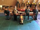
Beautiful, Casey.I’ve been busy painting more figures
By the way, how many of these do you have now? I think I've seen quite a few.
casey jones snr
Registered
Jasper, I now have 22 of the figures.Beautiful, Casey.
By the way, how many of these do you have now? I think I've seen quite a few.
Great idea Jon. I'll have to make one too! I've been using a much to large pulley puller and a slotted piece of wood which works but is a real PITA.. I like yours a whole lot better.Thus I made a G Scale Wheel and Gear puller today.
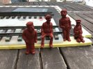
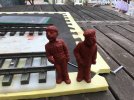
Paul, looking at this latest batch of painting, your methods are improving all the time. Superb job.I’ve been busy painting more figures:-
View attachment 271154View attachment 271155View attachment 271156
They are ”Short Staff” figures from Roundhouse Engineering.
Chris Vernell
45.29 N, 75.75 W
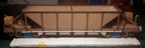
Got started on applying Cambrian rivet heads to my hoppers. One side and one end done before my eyes crossed.
Had to find fresh elastic for my magnifying headgear as the original had lost its stretch. Oh well, it had a long career.
Lunch and then back to the bench.
Post prandium: Finished applying rivets to the first of two hoppers. Also managed to knock over the vial of lacquer thinner -- twice
 . It took the finish off my cutting mat, but no worse
  .
.
Had to find fresh elastic for my magnifying headgear as the original had lost its stretch. Oh well, it had a long career.
Lunch and then back to the bench.
Post prandium: Finished applying rivets to the first of two hoppers. Also managed to knock over the vial of lacquer thinner -- twice
Last edited:
Grrr day, had my Trainline 0-6-0 on the bench to add a programming socket. In truth I think I had problems programming the DCC on this thing when I got it having installed a DPDTCO to link via Battery to Track. As the Track pickup was so rubbish I assumed that was the issue so today tried a Plug with direct link to the chip. Still will not talk to the chip on my Z21, this has never been fased with any chip and triple checked to connections and links with a meter. Dashed waste of time. I just wonder if the chip which is a Zimo MX696 could be locked in some way?
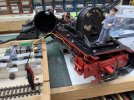
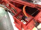


LGB-Sid
Registered
My eMotion XL came today so a quick basic wire job and it was time to see if Grumpy Bear actually runs  before I make some slight changes to the running gear . 20+ laps around the Garden slight knocking when it corners , sounds like a bad wheel bearing

Piko don't half put a lot of free play on the centre set of wheels up and down and side to side, I am sure the knocking comes from them on the corners, might restrict the movement a bit and see what effect that has.
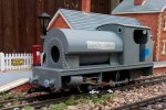
I did make a video but the site doesn't like my video.
Piko don't half put a lot of free play on the centre set of wheels up and down and side to side, I am sure the knocking comes from them on the corners, might restrict the movement a bit and see what effect that has.

I did make a video but the site doesn't like my video.
Thanks Phil, I have 2 switches one that does the battery and the other that does the link to DCC. Both have plugs but different sizes so as not to mix the up!Hi Jon,
If you are feeding into the charging socket?? - Is it not wired to disconnect the electronics, and ONLY charge the battery???
Just a thought..
PhilP.
The DCC link for Programming a DPDTCO made up so that one way is via Battery the other via the plug to link to DCC Programming Track via the said plug that is only for this. So when doing this I triple checked everything as that switch off tab when plugged in is an easy mistake to make. Anyway just rechecked that and with the plug in the link to the DCC side is sound so still at a loss on this one, still the loco works and whilst I had it to bits I reversed the Motor contacts which was one of the jobs I was going to do via DCC. The other job I wanted to do was to kill momentum, that will still have to wait for another day. Just fed up with pulling this apart and putting it together! Every time I do another bit if detail gets trashed to be replaced by sundry bits of wire. Some of letest crop of repairs watingba little dab of matt black.
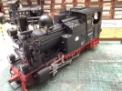
LGB-Sid
Registered
Knocking on corners, is quite often something catching within the motion..
How much of this one is resin-printed, please?
PhilP.
I think when it corners the central wheels are dragging the piston rod bars sideways and they are catching, hard to see as it's moving but I will make a small change and see if it cures the problem. It is all FDM Printed apart from the buffers which are Resin, there will be resin printed detail added later.
Rhinochugger
Retired Oik
I'm with Philp, rather than reducing the axle play, it might be better to increase the side play in the motion - in other words, while the axle has enough side-swipe in the chassis / axle bearings, it shouldn't take the con-rod with it; so allow the con-rod more side-swipe so that it can remain straight while the axle moves from side to side.I think when it corners the central wheels are dragging the piston rod bars sideways and they are catching, hard to see as it's moving but I will make a small change and see if it cures the problem. It is all FDM Printed apart from the buffers which are Resin, there will be resin printed detail added later.
If this isn't possible, take the flanges of the centre wheels - make them blind drivers, it won't affect the tractive effort in any way.
LGB-Sid
Registered
It looks like the bar from the central wheel to the slider catches the screw head on the front wheel bar on cornering when the two pass one another, due to the sideways play and the fact that my triple connection bar is a bit thicker than normal, so will re-print that .5mm thinner today, then see if I can remove a bit off the front wheel screw mount I made then add another .5mm onto the slider rear mount to move it out a bit more to see if that all gains enough space. Wish I had ordered some of the staniz type wheel bolts now as they have very thin flat hex heads. that would have gained at least a mm on its own, carnt find anything like them elsewhere. It's all part of the fun of drawing something up from scratch, and it would probably have been better if the center wheels were more contained with no flange.
If you look at a Piko BR80 the connection to the piston rod comes from the back wheels rather than the center, which would have been a lot eaiser to control the clearance but wrong for the engine I am making
If you look at a Piko BR80 the connection to the piston rod comes from the back wheels rather than the center, which would have been a lot eaiser to control the clearance but wrong for the engine I am making
Rhinochugger
Retired Oik
If you look at a Piko BR80 the connection to the piston rod comes from the back wheels rather than the center, which would have been a lot eaiser to control the clearance but wrong for the engine I am making
Can you get someone to turn the wheels on a lathe and take the flanges off?

