Rhinochugger
Retired Oik
Now you're showing your ageGetting back to the issue of the human race, I think these guys were spot on. After this, we can go back to the workbench thread's main reason for being, if so desired.....
Now you're showing your ageGetting back to the issue of the human race, I think these guys were spot on. After this, we can go back to the workbench thread's main reason for being, if so desired.....
Getting back to the issue of the human race, I think these guys were spot on. After this, we can go back to the workbench thread's main reason for being, if so desired.....
Now you're showing your age
As the man said....It was only 1969
I thought it was a bit risky trying to get the thread back on trackI thought it was me causing the forum trouble yesterday, by posting a picture of full frontal vice!
I seem to have got away with it.
Malcolm


Hm I wonder if RS may give you a clue, though likely different they will have gen sheets for lead-free solders I am sure.I seem to 'not be getting on with' lead-free solder, at the moment..
I am thinking it might be down to the higher ambient temperature in the conservatory?
Now, do I reduce the temperature of the 'iron, or increase it (which would maintain the difference between ambient and working-temperature of the iron)?
Unfortunately, the solder came from Maplins, so I do not have access to any specifications, or suggest temperatures.
PhilP
Tight, still, but it seems to be OK:
View attachment 314956
Good old try and see probablyI seem to 'not be getting on with' lead-free solder, at the moment..
I am thinking it might be down to the higher ambient temperature in the conservatory?
Now, do I reduce the temperature of the 'iron, or increase it (which would maintain the difference between ambient and working-temperature of the iron)?
Unfortunately, the solder came from Maplins, so I do not have access to any specifications, or suggest temperatures.
PhilP
Lead free solder is generally a higher melt point, and assuming it is pre-fluxed as it uses a different flux. Also the MOD did some testing about compatibility with leaded solder, so if you are using pre-tined components then bi-metal corrosion and adhesion can occur (can't reveal my source or I would have to kill youI seem to 'not be getting on with' lead-free solder, at the moment..
I am thinking it might be down to the higher ambient temperature in the conservatory?
Now, do I reduce the temperature of the 'iron, or increase it (which would maintain the difference between ambient and working-temperature of the iron)?
Unfortunately, the solder came from Maplins, so I do not have access to any specifications, or suggest temperatures.
PhilP
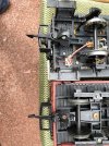
Just a photographic illusion, I suspect, perhaps because the old US-style freight car has no central buffer? These are the two I used to test clearance - an ancient LGB 4 wheel coach and Bachmann cattle car, fitted with hook and eye coupler:on this pic i noted something never seen before.
the coupling. seems to shorten the gaps between wagons.
looks like they could be shortened LGB couplers.
do you happen to have a pic or two from the underside?
thanks, korm

