What happened at your workbench today?

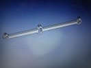
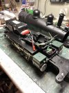
Whilst sorting out a recently acquired LGB loco....an ‘American’ 060 diesel, .the plastic coupling rod broke in half!

I wasn’t juggling with the loco at the time, just replacing a skate spring, and fitting a new traction tyre. In my foam cradle.

The rod has been broken before, and glued. My plastic glues don’t seem to be doing the job ( ema plastic weld or Tamiya liquid poly )

I’ve half glued it, but I know it won’t last.

Anyone got a spare.....one will do...? Possibly the same as the 060 Corpet steam loco....

Malcolm

View attachment 315441
You need to talk nicely to someone who could 3D print one for you ;);)
 
Might be time to make a new one, perhaps from steel. It might not look the same but would certainly be more robust. 10x2 mm from BnQ?
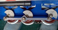
The rods only drive the middle ( sprung ) centre axle, as the outer axles are driven by gears from the motor. The flycranks are plastic, and a metal rod would have to be very well made not to damage the plastic bearings on the cranks. Early Stainz’ used to have metal valve gear with plastic bearings.

I did a quick search for replacement rods, Train-Li have them for $13 each. I do have a couple of ways of getting them to the uk, probably doubling the actual cost!

Malcolm

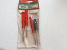
PS, this toolkit came in handy for the hex screw driver
30295EF4-AF68-4A15-85A0-0902CE3AFEC0.jpeg
 
The rods only drive the middle ( sprung ) centre axle, as the outer axles are driven by gears from the motor. The flycranks are plastic, and a metal rod would have to be very well made not to damage the plastic bearings on the cranks. Early Stainz’ used to have metal valve gear with plastic bearings.

I did a quick search for replacement rods, Train-Li have them for $13 each. I do have a couple of ways of getting them to the uk, probably doubling the actual cost!

Malcolm

PS, this toolkit came in handy for the hex screw driver
View attachment 315488
You certainly can't get enough hex nut runners! Or screwdrivers, knives, hammers, pliers.........
 
Might be time to make a new one, perhaps from steel. It might not look the same but would certainly be more robust. 10x2 mm from BnQ?
Or even aluminium, easier to work.
 
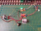
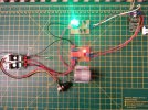
Had a request for an update to a project from back in 2012, alternative motor and speed control for the Track Cleaning Motor.
Relay activation from the F1 Function Key and only operates the cleaning motor when the Track Cleaning Loco travelling forward.
Cleaning motor speed controllable from the speed controller.

LGB 55021 F1 Relay Motor Control OFF.jpg


LGB 55021 F1 Relay Motor Control ON.jpg
 
Had a request for an update to a project from back in 2012, alternative motor and speed control for the Track Cleaning Motor.
Relay activation from the F1 Function Key and only operates the cleaning motor when the Track Cleaning Loco travelling forward.
Cleaning motor speed controllable from the speed controller.

View attachment 315529


View attachment 315530
That makes good sense :nod::nod::nod:
 
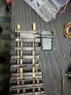
Installing a few of the new massoth switches today.

IMG_0982.jpeg
 

Attachments

  • IMG_0983.jpeg
    IMG_0983.jpeg
    918.9 KB · Views: 0
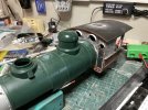
I had already used a solder tube to make a Spanish post box, now I found a new use for slices of one, on the cab mod of my latest Big Hauler bash.cab_bodge.jpg
 
I have been converting a PIKO V20 to battery RC with some bits I had around ( Arduino Nano Every brain, Pololu motor controller, Loksound V5Fx ).
Attempting to get the Loksound Fx to work as a 'digital' sound card. Tried a fairly hacky way of doing it by using the function outputs to 'switch' the 8 bits of a speed byte via opto-couplers, read by the Arduino. However due to ESU function output jankyness it doesn't quite work. One of the outputs is inverted, though there is nothing in Lokprogrammer / CVs to support that. One of the other outputs tends to float a bit, causing that bit to flip on and off, meaning the speed signal sent to the motor is all over the place. Shame really as it would make a nice sound card for battery RC locos.

Have a Lokpilot to go in my tender loco (when I get round it it) so thought I would see how that faired pairing with the Loksound.
I have discovered that sharing the 'drive hold' function is not possible without external parts (again, opto-coupler to the rescue) and sharing of drive lock is completely impossible without changing the ESU firmware - that's not going to happen. Without the ability to share these functions, getting a Loksound and Lokpilot to work together doesnt really work, the drive sounds are out of sync.

8NheZQC.jpg
 
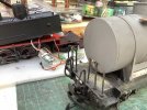
At last weeks Operating session I was informed that the Tank Wagon I created recently had nowhere to put an ‘End of Train’ marker. Post #15 on this thread shows the build.
Another new wagon where this has been forgotten! So sorted that out today. All the bits on the bench awaiting soldering up.
IMG_7438.jpeg
In place before some bkack paint, now back in service.
IMG_7439.jpeg
 
Offer accepted! It will be interesting to see how robust it is around the ‘weak point’ on the centre axle.

Malcolm
In theory .............. it should hold up. despite the oval hole, the work is done pushing and pulling along the length of the rod.

I s'pose the shoulders - where the oval hole opens up a bit - are key :nod::nod:
 
Big sigh of relief this morning, as I found the battery pack I hoped would replace the Big Hauler loco weight does indeed fit as intended. Now to secure it and squeeze in the other bits and pieces...
bh_batt.jpg
 
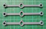
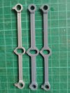
Printed the con rods for Brixham Brixham .

3 variations. One of them has too much 'meat'.

One of them has an oversize slotted hole after reducing the 'meat'. Not sure why that happened but I had to modify the design again to get the slot height correct.

The other one is getting there!

Printed in ABS because it is tougher and not so brittle.

The original LGB con rods have a slotted hole at the long end although the extra width is not obvious at 0.8mm long. I only noticed when measuring with my caliper. They also have very generous clearance loles for the crank pins. The crank pins are 5 mm diameter and the con rods have 6 mm holes for the con rods.
The printed ones have 5.5 mm holes.

IMG_20230715_095811353~3.jpg


IMG_20230713_173417292_HDR~2.jpg
IMG_20230714_154657636.jpg
Lost the fine detail of the original, ABS doesn't like fine detail, at least it can be done!

Alan
 
3D printing does look like it could be a game-changer, for difficult to source parts?

Things can only improve, as the equipment improves, and more 'exotic' materials are developed that can be printed.

PhilP
 
Back
Top