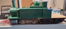
Stuffing in the Rx, Sound and Speaker?Hmmmmm....
Somebody paid good money, to someone to fit radio control to their loco:
View attachment 317266
Still, it is only a few batteries and DC..
What could possibly go wrong?
(look between the green tape to the left, at the lower batteries..)
PhilP
You are using an out of date browser. It may not display this or other websites correctly.
You should upgrade or use an alternative browser.
You should upgrade or use an alternative browser.
What happened at your workbench today?
- Thread starter Henri
- Start date
That nice Mr
 3 minutes of fame
popped in to see me last Friday with some samples of his 3D track and Vac Pipes (he passes the nits on his commute when visiting certain work assignments), a deal was struck for Vac Pipes and 30 duly arrived today. Thanks for the quick turnaround 3.
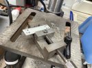
So for the pipes as I intended to fit all LGB to some vehicles and the 3D ones to others I made a jig for hole and placement drilling. The 4 holes are to do LGB large and 3D ones each side. As ever with LGB things do not always go to plan and the jig is a ‘sort of help’. So far as I can see now there appear to be at least 4 different type on LGB stock, possibly more so I will be upping everything to 4 vac pipes but doing less work on swopping things around. Here is the jig I made, 3mm holes for the LGB one seen on the van below. 2.5mm holes for the 3D ones.
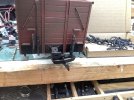
Below you can see the first fitting with original ‘flat’ type on the right and 3D ones to the left. All the 3D ones I am fitting will have a splodge of UHU Power on the inside of the buffer beam.
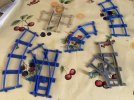
Finally the examples of 3D printed track delivered for laying out a possible small indoor 45mm railway, I will be using the mid-range curves to the left of the picture, those and the point appear to accommodate my 2 battery Steam Trams quite well. The smaller rad curve and point to the right are just mad, but my motorised skip will run on them quite happily. This link shows a similar use in 32mm gauge.
No excuses for not having space for a railway, but no Big Boys or even Stainz allowed!
So for the pipes as I intended to fit all LGB to some vehicles and the 3D ones to others I made a jig for hole and placement drilling. The 4 holes are to do LGB large and 3D ones each side. As ever with LGB things do not always go to plan and the jig is a ‘sort of help’. So far as I can see now there appear to be at least 4 different type on LGB stock, possibly more so I will be upping everything to 4 vac pipes but doing less work on swopping things around. Here is the jig I made, 3mm holes for the LGB one seen on the van below. 2.5mm holes for the 3D ones.

Below you can see the first fitting with original ‘flat’ type on the right and 3D ones to the left. All the 3D ones I am fitting will have a splodge of UHU Power on the inside of the buffer beam.

Finally the examples of 3D printed track delivered for laying out a possible small indoor 45mm railway, I will be using the mid-range curves to the left of the picture, those and the point appear to accommodate my 2 battery Steam Trams quite well. The smaller rad curve and point to the right are just mad, but my motorised skip will run on them quite happily. This link shows a similar use in 32mm gauge.

No excuses for not having space for a railway, but no Big Boys or even Stainz allowed!
viaEstrecha
Spanish metre gauge in G scale (on the cheap)
Hoping you'll be so busy, playing with all those new toys, you'll not have time to make operating sessions any more fiendishThat nice Mr3 minutes of fame popped in to see me last Friday with some samples of his 3D track and Vac Pipes (he passes the nits on his commute when visiting certain work assignments), a deal was struck for Vac Pipes and 30 duly arrived today. Thanks for the quick turnaround 3.
So for the pipes as I intended to fit all LGB to some vehicles and the 3D ones to others I made a jig for hole and placement drilling. The 4 holes are to do LGB large and 3D ones each side. As ever with LGB things do not always go to plan and the jig is a ‘sort of help’. So far as I can see now there appear to be at least 4 different type on LGB stock, possibly more so I will be upping everything to 4 vac pipes but doing less work on swopping things around. Here is the jig I made, 3mm holes for the LGB one seen on the van below. 2.5mm holes for the 3D ones.
View attachment 317341
Below you can see the first fitting with original ‘flat’ type on the right and 3D ones to the left. All the 3D ones I am fitting will have a splodge of UHU Power on the inside of the buffer beam.
View attachment 317342
Finally the examples of 3D printed track delivered for laying out a possible small indoor 45mm railway, I will be using the mid-range curves to the left of the picture, those and the point appear to accommodate my 2 battery Steam Trams quite well. The smaller rad curve and point to the right are just mad, but my motorised skip will run on them quite happily. This link shows a similar use in 32mm gauge.
View attachment 317340
No excuses for not having space for a railway, but no Big Boys or even Stainz allowed!
FatherMcD
Registered
Looks like the wire between the batteries has come un-soldered?Hmmmmm....
Somebody paid good money, to someone to fit radio control to their loco:
View attachment 317266
Still, it is only a few batteries and DC..
What could possibly go wrong?
(look between the green tape to the left, at the lower batteries..)
PhilP
Yes..Looks like the wire between the batteries has come un-soldered?
But there is nothing between the various sets of cells, and each set are wired in series, not fastened down, so the potential (no pun) for shorts between different points in the pack.
Difficult to get a solid joint onto button-top cells, with a soldering iron.
PhilP
3 minutes of fame
3d printing, electronics and trams
Well, we wouldn't want you getting bored would we??That nice Mr3 minutes of fame popped in to see me last Friday with some samples of his 3D track and Vac Pipes (he passes the nits on his commute when visiting certain work assignments), a deal was struck for Vac Pipes and 30 duly arrived today. Thanks for the quick turnaround 3.
So for the pipes as I intended to fit all LGB to some vehicles and the 3D ones to others I made a jig for hole and placement drilling. The 4 holes are to do LGB large and 3D ones each side. As ever with LGB things do not always go to plan and the jig is a ‘sort of help’. So far as I can see now there appear to be at least 4 different type on LGB stock, possibly more so I will be upping everything to 4 vac pipes but doing less work on swopping things around. Here is the jig I made, 3mm holes for the LGB one seen on the van below. 2.5mm holes for the 3D ones.
View attachment 317341
Below you can see the first fitting with original ‘flat’ type on the right and 3D ones to the left. All the 3D ones I am fitting will have a splodge of UHU Power on the inside of the buffer beam.
View attachment 317342
Finally the examples of 3D printed track delivered for laying out a possible small indoor 45mm railway, I will be using the mid-range curves to the left of the picture, those and the point appear to accommodate my 2 battery Steam Trams quite well. The smaller rad curve and point to the right are just mad, but my motorised skip will run on them quite happily. This link shows a similar use in 32mm gauge.
View attachment 317340
No excuses for not having space for a railway, but no Big Boys or even Stainz allowed!
Chris Vernell
45.29 N, 75.75 W
You do realize his given name (the one he keeps quiet about) is Mephistopheles?Hoping you'll be so busy, playing with all those new toys, you'll not have time to make operating sessions any more fiendish
3 minutes of fame
3d printing, electronics and trams
3 minutes of fame
3d printing, electronics and trams
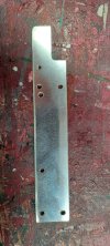
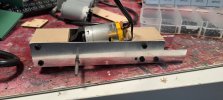
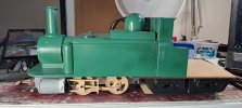
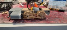
I think the rear wheel can go about 10mm further back. It's all looking a bit toy train currently.Work continues on the Double Fairlie. A prototype chassis has been machined out of aluminium, along with 3d printed motion and wheels etc. A quick trial fit, but looking OK so far.
View attachment 317377View attachment 317378View attachment 317379View attachment 317380
Easy enough to modify the file, and cut out a couple more frames, but for the sake of one set of holes, I will manually mark and drill them.
3 minutes of fame
3d printing, electronics and trams
playmofire
Registered
Sorry, I missed the "Handle with Care" sign.Not really from my workbench, but something that needed tweaking on my workbench.
Rhinochugger
Retired Oik
Even a hungry Aristo motor would run OK on sub-Cs and that's only 18v there by my reckoning. 19.2v of sub-Cs would give better performance and you don't have to solder the batteries yerself.Hmmmmm....
Somebody paid good money, to someone to fit radio control to their loco:
View attachment 317266
Still, it is only a few batteries and DC..
What could possibly go wrong?
(look between the green tape to the left, at the lower batteries..)
PhilP
Does make you wonder sometimes
Rhinochugger
Retired Oik
Relying entirely on the thickness of the insulated wire to keep the cell ends apart - I mean, there are professionals, amateurs and contestants for the Darwin awardYes..
But there is nothing between the various sets of cells, and each set are wired in series, not fastened down, so the potential (no pun) for shorts between different points in the pack.
Difficult to get a solid joint onto button-top cells, with a soldering iron.
PhilP
Just as well they're only playing with small volts. The total dipsticks I see at work aiming for the Darwin Award, intend to take with them anyone within ½ mileRelying entirely on the thickness of the insulated wire to keep the cell ends apart - I mean, there are professionals, amateurs and contestants for the Darwin award
I did a small, and unscientific, experiment involving wood glue paint and sealant on a bit of plywood. I found that both the PVA types of glue (Gorilla and Evo-Stik) I used would stick very well to the paint, but not so well to the sealant. Which comes in handy for my coach building endeavours
Rhinochugger
Retired Oik
Yes, you're messing around with two, quite complex materials there. PVA glue, although it is water soluble, has various side properties - one of which is that it can be used to shrink tissue paper on model aircraft instead of dopeI did a small, and unscientific, experiment involving wood glue paint and sealant on a bit of plywood. I found that both the PVA types of glue (Gorilla and Evo-Stik) I used would stick very well to the paint, but not so well to the sealant. Which comes in handy for my coach building endeavours
Sealant - if you're talking silicone rather than acrylic, will not usually accept any coating for any length of time
Rhinochugger
Retired Oik
I was talking to our builder about the new trend for spraying UPVC windows in delicate shades of grey and beige, and he said that while the paint adhered to the UPVC very well, and with decent longevity, the big downside was that it wouldn't weather well on the sealant around the edges.It was acrylic spray stuff, which surprised me, I thought it would stick better to that than the paint. Still we live and learn
Nothing much adheres to silicone - even more silicone

