You are using an out of date browser. It may not display this or other websites correctly.
You should upgrade or use an alternative browser.
You should upgrade or use an alternative browser.
What happened at your workbench today?
- Thread starter Henri
- Start date
Northsider
Modelling the Northern half of the Isle of Man
I'm green with envy. Those puns are sharp: like a knife through putter.Yes. you've got to go a fair way to beat him.
David
Fezwig
Just a man in the middle of a complicated plan.
Rhinochugger
Retired Oik
Steam them - might be enough to hold the pipe over a boiling pan, or even the kettle - with some gloves on of courseErr, ahem, after a lie down in a dark room, back to the workbench.
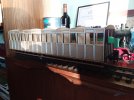
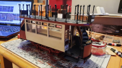
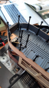
Spent a dull day putting on bolts on the outside of the frames, if I'd seen yesterday's post, they'd be even more wobbly
View attachment 279411
Also cut 2 piece of ply for the roof and put them inside a bit of pipe to put a bit of curve on them
View attachment 279412
3 minutes of fame
3d printing, electronics and trams
Chris Vernell
45.29 N, 75.75 W
The chassis for the latest batch of three hopper wagons are just about done.
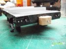
I've run out of AnDel coupling blocks, so I cut 3/4" sections off a 7/16" square wooden dowel ...
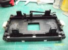
and epoxied them to the HLW buffer beams with #1 hex-head screws for reinforcement.
The single-shoe brake gear is more leftover AnDel parts with homemade hangers.
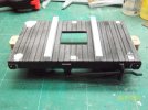
I have one more HLW wagon kit to work with. I'm still pondering what to bash it into: A gunpowder wagon is one possibility.

I've run out of AnDel coupling blocks, so I cut 3/4" sections off a 7/16" square wooden dowel ...

and epoxied them to the HLW buffer beams with #1 hex-head screws for reinforcement.
The single-shoe brake gear is more leftover AnDel parts with homemade hangers.

I have one more HLW wagon kit to work with. I'm still pondering what to bash it into: A gunpowder wagon is one possibility.
Fezwig
Just a man in the middle of a complicated plan.
Hm would love to see the Health and Safety manual for that procedure, War and Peace comes to mind.If I get shouted at, it'll be your fault
View attachment 279441
It's a good job Miss Artois has vanished into the bathroom, should be safe for the next hour
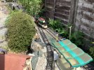
I managed to smash a few of those top parts when putting the wire in, replacing a few with soldered up tubing. Just the thing for some more 3D modeling if you suffer as I did. The resulting bodges were mostly hidden by an Advertising Hoarding. Mine has been modified as a Steam Tram Trailer.
3 minutes of fame
3d printing, electronics and trams
Interesting regarding the wire into the supports. It all feels quite robust and my main concern will be filling the gaps left, as the slot for the wire is quite large. I like what you have done with the kit. Other than lighting and motorising, mine will be pretty standard.Hm would love to see the Health and Safety manual for that procedure, War and Peace comes to mind.
I managed to smash a few of those top parts when putting the wire in, replacing a few with soldered up tubing. Just the thing for some more 3D modeling if you suffer as I did. The resulting bodges were mostly hidden by an Advertising Hoarding. Mine has been modified as a Steam Tram Trailer.
View attachment 279443
3 minutes of fame
3d printing, electronics and trams
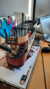
Yesterday and this morning has been mainly devoted to wood bending and swearing...
I pre-painted the boards and then once fully dry, I sat them in hot water for an hour before carefully bending them around a tin of varnish to give the approx shape. Once they had naturally dried out, I undid the clamps and fitted them. It took a couple of attempts, but I am reasonably happy with the result. Now just to sand, paint and varnish prior to fitting the transfers. Final jobs will then be seat construction, lighting and final fettling.
I pre-painted the boards and then once fully dry, I sat them in hot water for an hour before carefully bending them around a tin of varnish to give the approx shape. Once they had naturally dried out, I undid the clamps and fitted them. It took a couple of attempts, but I am reasonably happy with the result. Now just to sand, paint and varnish prior to fitting the transfers. Final jobs will then be seat construction, lighting and final fettling.


Rhinochugger
Retired Oik
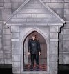
Sadly there are many local churches where people have been cared off - it's not always the vicar, thoughToday the Church at Caluna finally got a vicar, not sure hes the right man for the job, hes going to scare the congregationbut at least that will save on Resin
View attachment 279538
Many people see the church as irrelevant, and in some ways it is, but the message is as relevant today as it ever was
All you need is a creaky door and yerrrrrrs on your sound cardToday the Church at Caluna finally got a vicar, not sure hes the right man for the job, hes going to scare the congregationbut at least that will save on Resin
View attachment 279538
Today the Church at Caluna finally got a vicar, not sure hes the right man for the job, hes going to scare the congregationbut at least that will save on Resin
View attachment 279538
Yup Drak finally got the job he was looking for.All you need is a creaky door and yerrrrrrs on your sound card
Fezwig
Just a man in the middle of a complicated plan.
Rhinochugger
Retired Oik
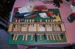
Que? - my good lady doesn't use clamps on the washingMore work, started to fit a ply roof on Monday, made a sub frame to fit so the roof can be removed
View attachment 279629
will post a pic of the roof removed when the second layer of ply has dried tomorrow, needless to say no washing was put on the line this week
David1226
Registered
Coal Office - I.P.Black
This is one of the four buildings that Father Christmas delivered Christmas 2020. This building, together with the scratch built coal staithes and storage bins and the modified 1941 Plymouth delivery truck, complete the coal yard installations of I.P.Black, Coal Merchant of Gernise End Station.
The building kit is from the British Outline Buildings range as supplied by Garden Railway Specialists (GRS) of Princess Risborough. I must admit that on opening the box my initial impressions were disappointing. The casting material was quite brittle and there was a lot of flash. I did find, however, that the flash was easily cleaned off with files and abrasive paper and once this was done my opinion of the model significantly changed. There is a wealth of detail, some of it very fine, incorporated into the moulded parts. The kit has the merit that with much of the detail moulded in, there are not many parts to assemble.
The basic building comprises the four walls, a roof, and chimney. I suspect these are modular, with the same mouldings for the side and rear walls being used on other buildings. Also included is a vacuum formed moulding of three lengths of channel, two channels are intended to be used as guttering, the third being used to form the roof ridge. There is also a length of plastic tube that can be cut to length to use as the downpipes. The roof on this building represents corrugated tin sheets. The instructions state that buildings with tin roofs do not require bargeboards or guttering, so two of the channels and the round tube are surplus to requirement. There is a length of square plastic rod that I have used to add additional window framing.
The strangest item included in the kit is a length of wall that appears to have no use or function. It is the same height as the building but is modelled as being a severely broken and derelict wall. It is very well moulded, as is, but gives the appearance that the slightest puff of wind would bring it crashing down. I cannot believe that such a wall would be left standing, it would immediately be knocked down on safety grounds. As it is only moulded on one side, it is difficult to see where such an item could be used on a layout. It has been consigned to the spares bin. I have also not used the ‘Coal Office’ cast signs as I shall make my own for I.P.Black. Being a coal office, the kit did contain three very well moulded and cast sacks of coal.
Using, as I suspect, modular walls, common to other buildings, the front edifice of the office is actually wider than the rear wall. This is not as strange as it sounds, but it did present one issue, which the builder is warned about it the instruction sheet, that the leading edge of the left hand wall fits very snugly (far too snugly) up to the left hand side of the shop window. This means that there is little or no lip for the edge of the window glazing. To get around this problem, for the sake of symmetry, I glued a length of 4.8mm square plastic tube down each side of the window frame. This does reduce the width of the window slightly, but it does provide the essential lip to hold and hide the edge of the glazing material.
As with the other cast resin buildings I have already assembled, the walls were glued together with Gorrilla superglue. Unibond Repair Metal was worked into the brick joints and scribed and a fillet of the same material was run down the inside corners to strengthen them.
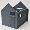
The bare shell of the building, the four walls with added window framing from plastic strip.
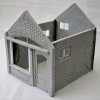
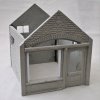
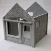
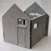
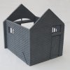
The shell of the building with a coat of spray plastic primer. It is my intention to paint the brickwork and to add some interior features before I put the roof on.
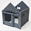
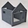
David
This is one of the four buildings that Father Christmas delivered Christmas 2020. This building, together with the scratch built coal staithes and storage bins and the modified 1941 Plymouth delivery truck, complete the coal yard installations of I.P.Black, Coal Merchant of Gernise End Station.
The building kit is from the British Outline Buildings range as supplied by Garden Railway Specialists (GRS) of Princess Risborough. I must admit that on opening the box my initial impressions were disappointing. The casting material was quite brittle and there was a lot of flash. I did find, however, that the flash was easily cleaned off with files and abrasive paper and once this was done my opinion of the model significantly changed. There is a wealth of detail, some of it very fine, incorporated into the moulded parts. The kit has the merit that with much of the detail moulded in, there are not many parts to assemble.
The basic building comprises the four walls, a roof, and chimney. I suspect these are modular, with the same mouldings for the side and rear walls being used on other buildings. Also included is a vacuum formed moulding of three lengths of channel, two channels are intended to be used as guttering, the third being used to form the roof ridge. There is also a length of plastic tube that can be cut to length to use as the downpipes. The roof on this building represents corrugated tin sheets. The instructions state that buildings with tin roofs do not require bargeboards or guttering, so two of the channels and the round tube are surplus to requirement. There is a length of square plastic rod that I have used to add additional window framing.
The strangest item included in the kit is a length of wall that appears to have no use or function. It is the same height as the building but is modelled as being a severely broken and derelict wall. It is very well moulded, as is, but gives the appearance that the slightest puff of wind would bring it crashing down. I cannot believe that such a wall would be left standing, it would immediately be knocked down on safety grounds. As it is only moulded on one side, it is difficult to see where such an item could be used on a layout. It has been consigned to the spares bin. I have also not used the ‘Coal Office’ cast signs as I shall make my own for I.P.Black. Being a coal office, the kit did contain three very well moulded and cast sacks of coal.
Using, as I suspect, modular walls, common to other buildings, the front edifice of the office is actually wider than the rear wall. This is not as strange as it sounds, but it did present one issue, which the builder is warned about it the instruction sheet, that the leading edge of the left hand wall fits very snugly (far too snugly) up to the left hand side of the shop window. This means that there is little or no lip for the edge of the window glazing. To get around this problem, for the sake of symmetry, I glued a length of 4.8mm square plastic tube down each side of the window frame. This does reduce the width of the window slightly, but it does provide the essential lip to hold and hide the edge of the glazing material.
As with the other cast resin buildings I have already assembled, the walls were glued together with Gorrilla superglue. Unibond Repair Metal was worked into the brick joints and scribed and a fillet of the same material was run down the inside corners to strengthen them.
The bare shell of the building, the four walls with added window framing from plastic strip.


The shell of the building with a coat of spray plastic primer. It is my intention to paint the brickwork and to add some interior features before I put the roof on.


David
Riograndad
Model Railroading, boats and oil painting,
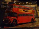
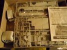
The Revel 1/24 Routemaster kit.Its been on top of the wardrobe in the spare room for at least 3 years and I thought it may be a good lock down time waster,so I opened the box to see what was going on and to check if I had the paints to complete it, yes I have so just might make a start on this pile of parts I have looked on utube at the builds done and a challenging kit to say the least and I noticed while checking it all out a few parts are out of shape but shouldn`t be too much of a problem to get back to normal,I think as its been in store for so long
 .
.


I had one of those. It's not that difficult, the hardest part is the top rear part over the stairs, I just couldn't get it to sit right, in fact most of the completed models of it I've seen never look quite right there. I think you need to position that piece before gluing the stairsThe Revel 1/24 Routemaster kit.Its been on top of the wardrobe in the spare room for at least 3 years and I thought it may be a good lock down time waster,so I opened the box to see what was going on and to check if I had the paints to complete it, yes I have so just might make a start on this pile of partsI have looked on utube at the builds done and a challenging kit to say the least and I noticed while checking it all out a few parts are out of shape but shouldn`t be too much of a problem to get back to normal,I think as its been in store for so long
.View attachment 279663View attachment 279664
Spent last night and today doing some maintenance on my LGB 2040 Kroc. This loco probably has at least 200+ hours of run time. One of the driver groups was having trouble running, particularly in reverse. At first I thought there was a problem with wear in the false jack-shafts. I spent quite a bit of time lubing and fiddling to no good end. I crudely checked the power of the motor with the kroc on its back by holding a finger against the turning wheels. The motor seemed much stronger running in one direction than the other. I had just read Tom White's post about motor current draw on another forum. One of the responses by Dan Pierce was a suggestion to essentially overhaul the motor if it was LGB old style with red and black end pieces that was at issue. Well, I didn't quite go that far with mine but I did literally blow the crap out of it with contact cleaner. Upon reassembly the fourth time (another story ) the troublesome drive block ran like a champ. After the great proficiency gained at disassembling this loco I figured I might as well clean the other motor too.
Now we come to the real purpose of this post. As long as I was working on the Krok I decided to put an operating red light in the dummy center light at the top of each cab. I'd been thinking of doing this mod to the kroc for awhile. I had some 3mm red LEDs on hand that I intended to use on baggage wagons as end of train lights and plenty of unused decoder function outputs.
I carefully drilled 1/16th inch pilot holes in the center of dummy lights from the outside using a pin vice. This was followed up with a 1/8 inch drill to open up a clearance hole for the body of the LED. Then from inside the cab, I drilled part way through the hole with a 5/32" drill which gave a shoulder against which the flange of the LEDs body could be seated. Here are a couple of shot of the install.
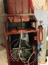
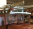
Here's a shot with it lit up.
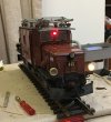
Now we come to the real purpose of this post. As long as I was working on the Krok I decided to put an operating red light in the dummy center light at the top of each cab. I'd been thinking of doing this mod to the kroc for awhile. I had some 3mm red LEDs on hand that I intended to use on baggage wagons as end of train lights and plenty of unused decoder function outputs.

I carefully drilled 1/16th inch pilot holes in the center of dummy lights from the outside using a pin vice. This was followed up with a 1/8 inch drill to open up a clearance hole for the body of the LED. Then from inside the cab, I drilled part way through the hole with a 5/32" drill which gave a shoulder against which the flange of the LEDs body could be seated. Here are a couple of shot of the install.


Here's a shot with it lit up.

Last edited:

