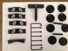
What have you been printing.

Yup! The easiest option as he also included a rig to hold the motor, battery and switch in the right position.


I'm just working on a Plan B - if that doesn't do the job then I might take you up on the offer...:)

Rik
I suppose another option, but would require a bit more work, would be one of those Tamiya model gearboxes - the one I bought came with four optional ratios, and you get a steel axle which would work the same way as driving off the motor shaft. It would take a bit of work, though :whew::whew:
 
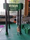
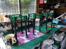
Working on the surport structure, work in progress. IMG_20200826_124051.jpgIMG_20200827_134455.jpg
 
I suppose another option, but would require a bit more work, would be one of those Tamiya model gearboxes - the one I bought came with four optional ratios, and you get a steel axle which would work the same way as driving off the motor shaft. It would take a bit of work, though :whew::whew:
I actually looked at that option. I have a Tamiya gearbox, but I couldn't work out how to tap into the final drive shaft and I've long since lost the instructions.

Plan B was to draw and print a pulley wheel to fit on the end of the shaft of one of those tiny gearbox motors which were on eBay a couple of years ago (might still be there). I bought three "just in case!". However, after a few abortive attempts to get it working, I gave up. Either the belt was too tight and there was too much friction on the beam engine shaft, or it was too slack and there wasn't enough friction for the belt to bite on the pulley wheels.

Plan C has been much more successful. I drew and 3d printed a cradle for the mini geared motor to allow it to sit inside the original motor clip. At first I had the motor shaft bearing directly on the outside of the flywheel as per the original arrangement. However, the was far to slow. So I dug out the wheel off a cheap toy from my bits box and forced it on to the end of the motor shaft. I've had to move the mounting for the motor, but it now rotates at a much more realistic speed.

I'm just painting the beam engine, so once that's done, I'll take another video so you can see it in action.

Rik
 
For some reason, I didn't hit the "Reply" button on the above post at the time, so it's now a bit delayed. I've now tweaked, soldered, painted and filmed.

The ex-toy-car wheel acting as a friction drive is a bit too apparent but I can hide that behind a strategically placed barrel or even an engineman figure. I think the speed is now about right - and the PWM controller allows me to fine tune that.

Rik
 
Now blogged the beam engine build for anyone who might be interested

Rik
 
My efforts are nowhere up the the quality and standard of Mike et al - maybe because my printer cost only £80 - or maybe because I'm not so skilled at setting up up properly. Prints which are mostly along the X and Y axis are acceptable
IMG_1085.JPG

So these ends and sides of my luggage van have turned out quite well. I've added a bit of detail with plasticard
IMG_1088.JPG

And mounted everything on my ubiquitous HLW chassis
IMG_1094.JPG

Almost finished ...
IMG_1100.JPG

Whereas these ridge tiles for the boneworks building were printed upright and so mostly along the Z axis and are heavily ribbed
IMG_1087.JPG

I think it's because the frame of my printer is made from 4mm ply and so, even though I've added extra framework to try and stabilise it, it still flexes a fair bit.

However, once installed, the ridge tiles seem to look OK
IMG_1106.JPG


Rik
 
IMG_1468.JPG
Well this is my offering, still learning a lot, my wife said she would like a rabbit printed, yesterday, first attempt came out 10mm tall! ...........so now I know how to re size in 'Cura' also, the railing, in the picture, would not print until I turned it round and laid it flat as it had been saved in the upright position
Dave
 
I've now finished titivating and painting the van.
IMG_1122.JPG

.
As you can see, it's quite a small model - I don't think the CDR luggage vans were quite this small, but I wanted it to look right proportionally.
IMG_1123.JPG

.
The 3D prints were 'bare-bones' so I added the detailing later using plasticard (see above).
IMG_1124.JPG

.
I'm quite pleased with how it turned out.

Rik
 
I decided to tinker with the drawings and have now added the extra detailing as part of the print.
IMG_1128.JPG

.
I've not done any tidying - this is how it has come off the printer.
IMG_1129.JPG

.
I've now printed sufficient parts to make another van.
IMG_1127.JPG

.
From my experience, curved roofs are a bit of a struggle for 3D printers. On the original model I used strips of 1.5mm plasticard as planks covered with a 0.5mm layer of plasticard. I opted for interlocking planks for version 2 of the van.
IMG_1135.JPG

.
They could be covered with plasticard, paper or fabric. I'll decided when I get to it.

Rik
 
And, of course, my source of ready to roll chassis has dried-up - ie the Hartland Loco Works mini series.

So, I decided to design my own version based on the dimensions of the HLW chassis.
IMG_1130.JPG

.
However, I've never been happy with the HLW solebars, so I redesigned them to look more UK-based.
IMG_1131.JPG

.
The can be fitted with Bachmann metal wheels as with the HLW wagons
IMG_1140.JPG

.
Either the usual 32mm wheels
IMG_1138.JPG

.
Or the smaller 24mm (?) wheels
IMG_1136.JPG

.
The smaller wheels looked better on the luggage van BTW

Rik
 
I've now finished titivating and painting the van.
IMG_1122.JPG

.
As you can see, it's quite a small model - I don't think the CDR luggage vans were quite this small, but I wanted it to look right proportionally.
IMG_1123.JPG

.
The 3D prints were 'bare-bones' so I added the detailing later using plasticard (see above).
IMG_1124.JPG

.
I'm quite pleased with how it turned out.

Rik
That railbus is very similar to the Clogher Valley one - very nice
 
IMG_1471.JPG
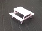
Ok , next print, as you can see, a picnic bench, this is from 'thingiverse' it is in 00 scale but dimensions changed to suit G scale. The only problem was that the first few lines across the seats and table top, sagged, but once several passes were made, it all looked good from the top. What I have found is that, to slide a 15 watt soldering iron over the loose strands, melts the filament back to shape, looks a bit untidy underneath but looks good from the top, which is where it will be viewed from.
Dave
Ps. I will ignore the comments about my wife's rabbit!!!
 
That railbus is very similar to the Clogher Valley one - very nice
They were one and the same - the County Donegal bought it from the CVR when they started investigating the feasibility of I/c power. I particularly liked this bus - partly because it was the smallest of the articulated railbuses and so I thought it would cope with my sharp curves and also because I really like the half cab.

Rik
 
Not as ambitious as other posts on the thread, but I'm feeling pleased with the outcome. I decided some of my through stations needed another running-in board as, at the moment they have only one in the middle of the platform rather than one at each end. So, a quick bit of fiddling with TinkerCAD and here's the result:

Two yet to be printed
Beeston Castle nameboard.jpg

.
Bickerton nameboard.jpg

.
..... and one done so far....
DSCI3507.JPG

.
The stations with island platforms have double-sided nameboards.

Got plenty of other 3D projects in the pipeline

Rik
Just seen the posts on the Creality Ender 3 Pro thread.

My nameboards are 116mm x 24mm x 3.5mm

My printer is an Anet A8 clone which I bought as a kit for £80. I've added a few enhancements since I built it such as a glass bed, an aluminium bed-mount, MOSFET boards for the heated bed and hot end, and belt tensioners. I've also added a couple of plywood sections to reduce Z-axis wobble and replaced the 4mm ply front and rear chassis members with 6mm ply as the originals were starting to bow.

I'm using Amazon Basics PLA 1.75mm filament (£17.50 / kg) and have a 0.4mm nozzle on the print-head. (Edited to correct nozzle size)

The above is the third attempt as the first two started to bend upwards at the ends. I tried increasing the width of the brim to improve adhesion but in the end I discovered the bed needed re-levelling (again). This is an issue with my cheapo printer. The bed seems to require re-levelling at regular intervals. Sometimes it can be a couple of weeks before it needs re-adjustment but this week it's needed to be done after each print. Not sure why, might be the vibration from the stepper motors or the plywood frame flexing (or both).

However, for £80 I expected it would be far from perfect.

Rik
 
Last edited:
Back
Top