Track making/making tracks: the good, the bad and the ugly, advice and thoughts wanted, explanation is giving(incl mistakes)

It is considered flange bearing if the INTENT is that the flange of the wheel rides in the bottom of the flangeway.

Yes, indeed, it clearly depends on the wheel flange.

If you study mainline/prototype switches, you will see that flange bearing frogs are common, but they rely on a consistent flange depth.

Our hobby has anything BUT consistent flange depths.

Now, if you "control" your environment and have all flanges the same depth, matched to flange bearing frogs, then it actually works very well, as there are indeed substantial benefits to a flange bearing frog.


But, my main point is that for those of us have rolling stock with widely varying flange depths, flange bearing frogs are not a good solution.

Again, the classification of a frog being flange bearing or not flange bearing is by design of the frog, and makes assumptions of the flange depth of the wheels running through it.

The classification of a frog changing because you use different wheels, some may ride in the bottom of the flangeway and some not is not correct... I get your point you could define things from how they operate, given different "inputs", but there is more to the frog geometry than flangeway depth, MUCH more....

Greg
 
A Lot of good info, hints tips and links....please don't think i am ungrateful cous i did not reply.
There is a lot of stuff to learn and to do!
This is not a project that holds one item....
I will get back to the turn out this week....
There are some solutions and changes made, please wait to you see the next result.
Thanks for sharing all the info! All of it.
 
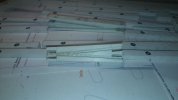
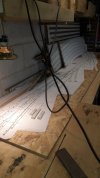
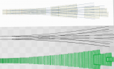
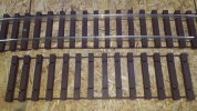
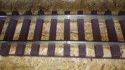
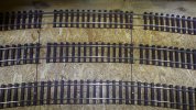
On a other site: templot, i found very good pictures of frogs.
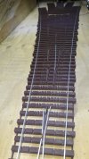
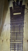
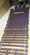
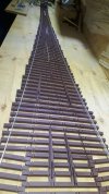
A couple of weeks ago a made a attempt to make them, i will save you the disasters, but i was close.
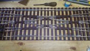
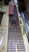
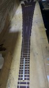
The ones shown in the pictures are from hardtop foam pvc, not the best material, i am waiting for my sheet of uv resistant extruded pvc.
Those frogs and those 3 x 3 way switches are for the "parking lot" inside the shed, so there will be no real abuse, if it will happen i will make new one's.

Bit by bit the experimenting is done.
Some things are left:
Throw bars, toes and the solenoids with micro switches.

20200622_115512.jpg20200622_115823.jpg

Sorry i am not a photo hero.

Best to all
 

Here is a link to a thread in made for making sleepers/ties production wise, believe it or not they are exact on measurement for the rails..
 
My apologizes for not posting for so long, i am very busy atm with building my house, i would like to have the roof completed before Christmas.
Plus a own company and a upcoming marriage......
I will report updates.

Stay save you all, watch out for that cranky ping-pong ball with a attitude, it is not a common flu.

Best to all
 
Track making FOUR . 0.... 5.0 is in the making.....
20210220_134010.jpg
20210220_134006.jpg
20210220_134057.jpg
20210220_133941.jpg
No problems just like the 3x3 way switch made out of wood, all is running clear and smooth.
Those sleepers are made with 3d printing abs, 6 times more expensive than wood but a heck more free time and way easier.
950 grams of abs was used.
3 weeks of cutting and trying wood against 3/4 hours of designing! and turn on your printer........ 12 hours of printing
In 5.0 it will be less abs and more wood incl the "throw bars?" made out of aluminium...the handle to switch lanes?..please help if you understand what i mean.
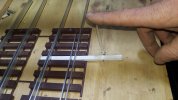
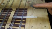
The device i put my finger on.

However i think the golden middle way is in those kind of experiments/works 50% wood and 50% abs.
The abs parts will incl frogs and such, the rest wood.
Thanks for reading, with best regards, Igor
 
Looking very good, many thanks for sharing on the wood part, what are you using as wood or what can you recommend.
 
Last edited:
Azobe, but at this point it is equal, azobe plus putty or 3d with abs, if you have the machinery and no printer azobe and polymax.

With best regars Igor.
 
i needed some relaxation....Next a 5 way switch..
Schermafbeelding 2021-05-02 184104.png
1:15 for the base/inside turnouts, i should have done 17 or 1:20....
radii inside turnouts 14 meters, outside turnouts 11.6 meters.
Overall length 2 meter 3
scale: proto 1:32
Need to make the frogs the safety rails and the frogs.
I need a other hour to shift the timbering in there correct places, due to the frogs.
Check clearance for the back of the flange and flange drive way, if neccecery i must adjust,
Cut out the rails, group frogs, convert into stl file
Print piece by piece
Than a good Sunday to make the tracks incl grinding point work...(educated guess 8 hours)

in the mean time i am 3 days behind my study:cry:, i will get to it it in time...
No i am not interested in a "stub switch"

Apparently there are two in the real world, somewhere in Germany and one in France.
Both languages i am not skilled in, can some German or France man chime in on this?
To get a "prove"of existence for me?

Yes i will post the results when i am done!
And to think of it, how i started 1.5 years ago....greener than grass....

With best regards Igor
 
Last edited:
Normally something like that would be in a congested space with many tracks.

So this would only be used in a switchyard, so the stresses are different I would submit.

Lower speed traffic, and less "hammering impact" from higher speed mainline trains, and also less side forces on the diverging routes.

Greg
 
Small update for a big 5way switch.
The overall length is adjusted to 2 meter 46.
Where there is a small aluminium strip in the middle of the track at the beginning, that is the point where the first points will start.
20210530_150034.jpg
20210530_150052.jpg
20210530_150121.jpg
Yes i made a counting mistake within the slicer process, have to adapt it...


20210530_150103.jpg
20210530_150148.jpg
I just put in some scrap pieces for the show, yes i think this is going to be very nice one.
And i hope it will do exactly what i want when it is finished.

I also "changed" my "system" of track making.
Instead of making complete 1 meter 20 pieces of track, i print only pieces of 33.5 cm of sleepers.
20210530_150719.jpg

If you look closely you can see that the strips are overlapping in a 33.5cm section, i think this would greatly improve the running quality and give the tracks some more ridgidness and even possible skip the need to fixate the tracks on the bed.
20210530_150643.jpg

I made them so far in: strait, 3m , 4m and 5m radii.
So far the 3d robot made me a ~60 meters, 1 meter a day if all goes well and with enough supplies and if the owner does not want to print something else:cool:
I also created "spacer pieces" to give a uniform and correct centre to centre distance for side/fiddle yards 10cm and 12.5cm and main tracks are 15 cm centre to centre
The spacer pieces for the curves still need some work as you can see, overall i am pretty pleased.

20210530_150307.jpg
For the tracks that are all-ready completed with wooden sleepers i created a "coupler" not yet printed.(run out of filament....duh o_O )
Will keep you updated ofcourse.

Woodworking is no match for a 3d printer for this level of precision....

Thanks for reading, i hope you enjoyed it
With best regards Igor.


Ps the chip-wood board is just a experimenting board.
Comments thoughts and ideas are as always welcome.
 
The trackwork you are making is amazing! The turnouts and x-overs look spectacular. Especially the 5-way. I'm looking forward to seeing that Russian monster you are working on in action too!
 
.
The trackwork you are making is amazing! The turnouts and x-overs look spectacular. Especially the 5-way. I'm looking forward to seeing that Russian monster you are working on in action too!
Thank you for the compliment. it was and still is a pretty steep learning curve if you want to go in full depth.
Especially when you want to have it "prototypical" correct.
Then it is not simply built a turnout expecting to run trouble free, yes i made a lot of mistakes....wasted a lot of hours and materials...still dont run a single train.
But the end result of what i am getting is what i want and even better(heck even my English improved).
My gauge is 45mm from flange to flange is 44mm that is meaning that also this is almost prototypical.
From flange to rail in prototypical is 10mm dived that with 32...

Speaking prototypical and the Russian monster (also some others, bigger-longer than the big boy)
They probably will get there own loop in the layout.
All the crossings and turnouts must be adapted for them if i want to let them run thru a 4 meter radii curve.
ATM the AA20 naked frame (wheels and motor only) can take a 4m radii curve, but flange to flange is 42mm, this will give a lot of problems with the guard rails and frogs.
41mm will give less friction, but than i must change the bearing surface of the wheels them self, and all will be out of order/does not look good also.
I am not fond of making concessions just to let it work.
To counter this problem I am planning to make a loop only for them with a minimum radii of 5 meters, with no connection to the other main lines, except for 3 or 4 diamond crossings.
They must go over some track work also, so a different level/ bridge must be implemented.
Those are the main reasons that i set the AA20 on hold and lack of time of course.
I hope i can proceed with her end this summer, i also need to build a 5 meter radii curve for testing.
All the mechanics involved needs to be adjusted, remeasured redesign, reprinted ect.
And yes it will be on you tube, gscale central is the first to know.
I am fully aware that if i succeed that i am the number 4 that was creating a working model....and the 3th with a true driving model, 2nd in true working prototypical model and the first with a working driving prototypical model on his layout.
This dream is ~15 years of age: to have a functional AA20 on a garden layout......i will get there, but when?

With best regards Igor
 
I started building, but i must admit due to his length and complexity it is a different cookie to eat...(2 meter 45 with 9 meter radii min and 13 meter max)

The main problem i run into is the unsupported length of the point, very difficult to work with or create.
"Stress test/weight bearing" (standing strait up)i am not so afraid for, but it can tilt/flip if you know what i mean.
Probably i will make two connections/bars( i lost the name for this piece) that hold the points in position.
For the next one with a similar length i will keep the points shorter.
Meaning that i must redesign a piece of the 5way switch.
Now this one has a real nice learning curve, almost perfect.
I am also considering to create a connection/bar "stand alone" on a sliding plate, to give it more rigidness.

I hope my story makes any sense, and you understand the problems i encounter at the moment....
But for every solution we have a problem :cool:

Also this 5way switch is a non practical eye catcher, more practical would be 3 3way switches built in together.
It will be shorter and in the same amount of space with the same radii (9 meters)you will gain 2 extra "parking lanes".
Never the less, this is a real fun project with a fun learning exercise to do, thank you again Tony (the person that "invented" this 5way)

With best regards Igor.

Sorry for the goof up of determine the right names for certain parts, had a very busy and stressful 2 weeks..
 
switch1.gif


and the frog itself has a lot of parts:
frog1.gif


Some more information about frog number versus angle in degrees, etc.

Greg
 
Back
Top